Learn what make trusses so special, the common truss types, the analysis methods by hand (Method of Joints and Method of Sections) and the design of the steel or timber truss components according to AS 4100 or AS 1170.2.
Introduction
What is a truss?
Trusses comprise of individual members connected at joints or nodes, creating a system of interconnected triangular elements that work together to form a rigid structure.
All loads and reactions are assumed to act only at pinned nodes, so no shear or moment is transferred between members. As such, truss members are subject to axial loading only which is beneficial because it means section sizes can be greatly reduced. Pin connections found in trusses are also much cheaper compared to moment connections, making trusses a relatively cheap option for a structure.

Trusses, the triangular marvel
Trusses are great because they:
- Achieve long-span structures such as bridges and stadiums.
- Minimise the weight of the structure by efficiently distributing loads through the triangular arrangement and thus enabling a lean member design.
- Carry heavy loads and provide robust support.
- Resist lateral load, such as wind or seismic forces. See our Design guide: Steel Bracing Systems for more information about how steel bracing can be effectively used in a lateral stability system.
\( \bf{1}\) Understanding from First Principles
Why are triangles and resulting trusses so effective at resisting load? These shapes perform well since no shear or bending develops in the system’s individual members when the load is applied at nodes. As the nodes are pinned, equilibrium at the connection is achieved through opposing vectorised loads in each connecting member.

Each member connected to the node will take a percentage of the imposed load in axial force proportional to its angular position. In the example above, the horizontal members take no vertical load, given they're at 90 degrees to the force F, but they take the horizontal reaction load induced by the angled chords.
Let's take a look at a 2D Truss in action! As you can see, there is no shear or bending in any of the members. The only force is axial!


\( \bf{2}\) Common Truss Types
There are endless arrangements for trusses. Various truss types have been developed to meet specific engineering requirements and architectural preferences. So form meets function in a fascinating array of prescribed designs.
Trusses are grouped into two main categories:
- 2D trusses (Planar trusses) - located on the same plane
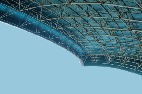
- 3D trusses (Space Frame truss)
Here, we'll just be focusing on Planar trusses.
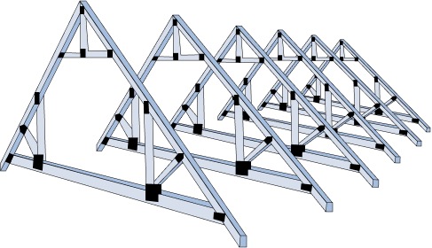
The different types of Planar Trusses each have different load transfer mechanisms. Below are the most common that you may have seen around! We will look at:
- Pratt Truss
- Howe Truss
- Warren Truss
- Fink Truss
- King Post truss
- Sawtooth (or Butterfly) Truss
- K-truss
- Cantilever truss
\( \bf{2.1}\) Pratt Truss
What is a Pratt truss?
The orientation of the diagonals in the Pratt Truss slant downwards to the middle of the truss, distinguishing it from the Howe truss.
Pratt Braces:
- Vertical Braces are in Compression
- Diagonal Braces are in Tension
Pratt Chords (also same in Howe and Warren):
- Top Chords are in Compression
- Bottom Chords are in Tension

Timber is often used in the vertical compression members, while steel is often used in the diagonal tension members.
Applications of the Pratt Truss
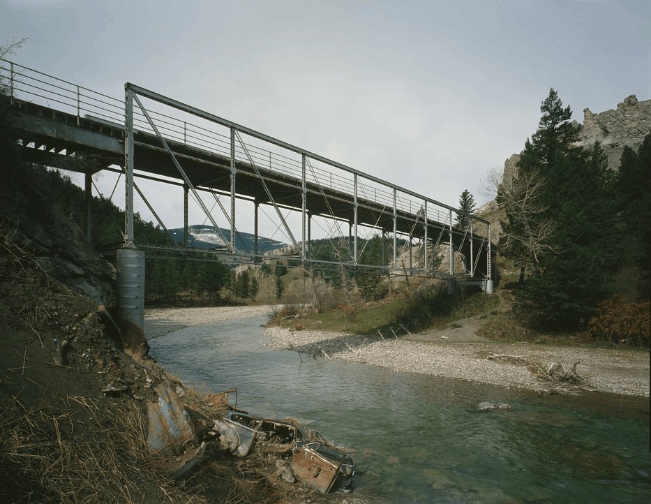
Built in 1897, with a length of 77 m, it is one of the rare Pratt half-deck bridges left in the US. Hence, it has been placed on the National Register of Historic Places. (Source - Jet Lowe/Library of Congress)
\( \bf{2.2}\) Howe Truss
What is a Howe Truss?
The Howe truss is a reverse version of the Pratt truss. Even though the only change is to the orientation of the diagonal braces, it behaves structurally very different to the Pratt truss.
Howe Braces:
- Vertical Braces are in Tension
- Diagonal Braces are in Compression

Applications of the Howe Truss
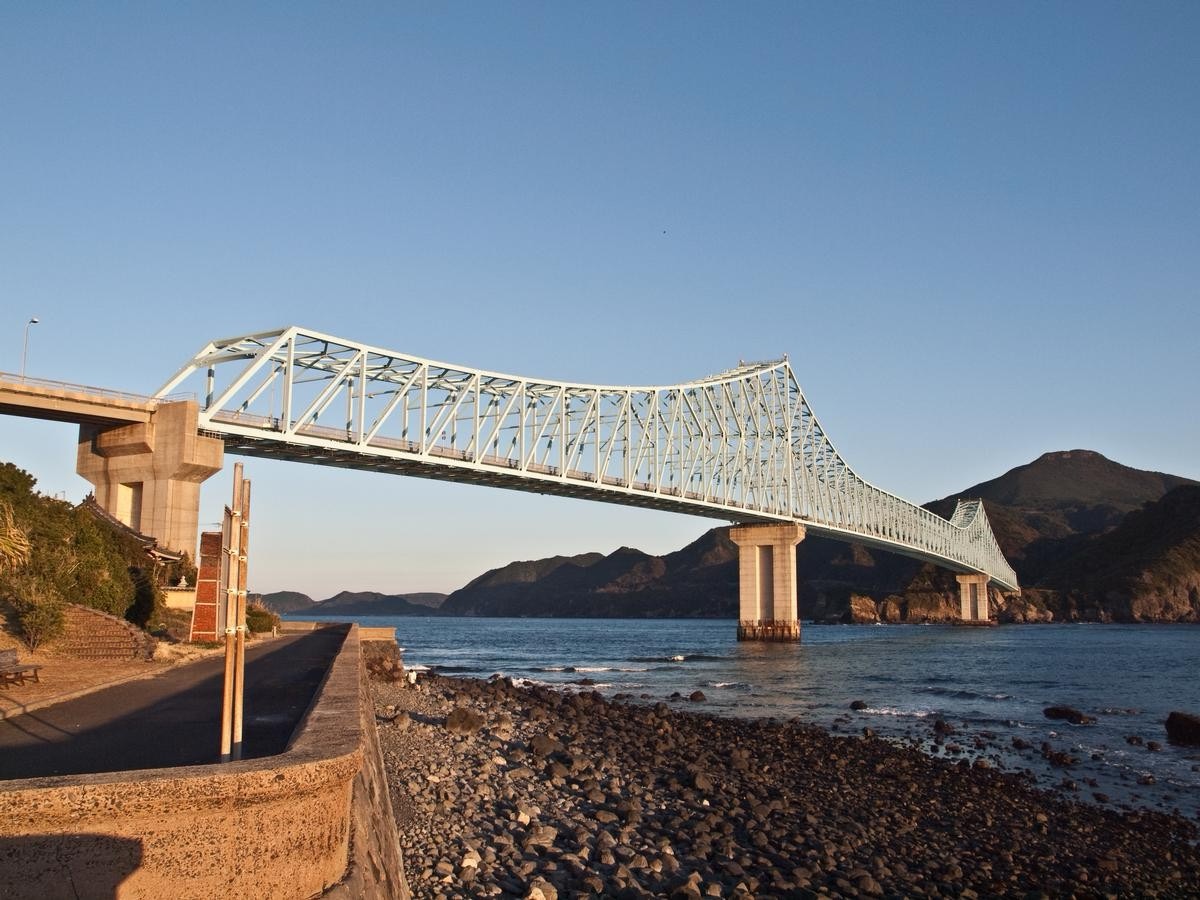
This bridge is the longest continuous truss bridge in the world, using a mix of Howe truss and K-truss with crossing trusses connecting two side trusses of the bridge. It has a main span of 400 metres.
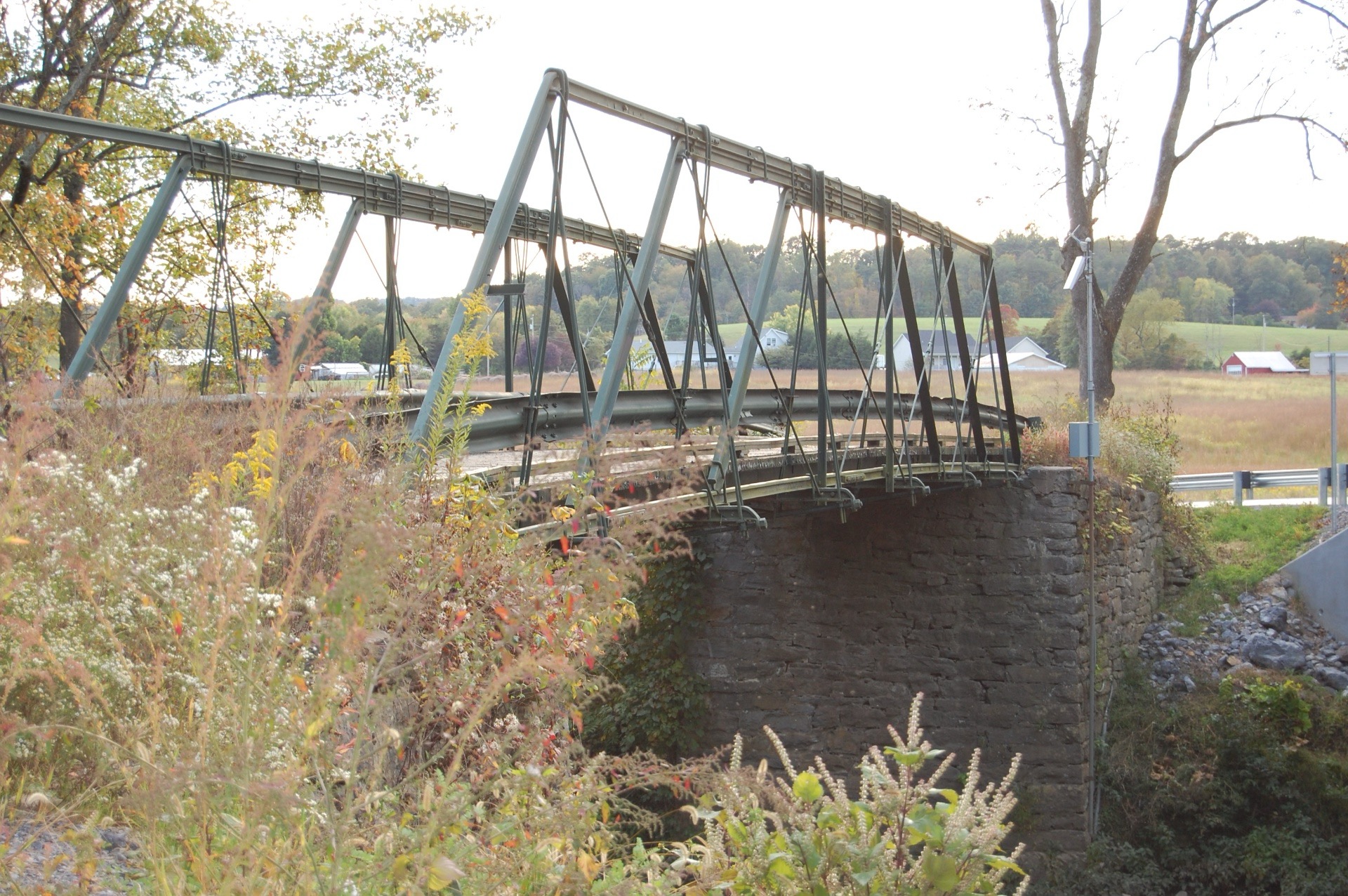
Built in 1892, With a length of 22 m, it is one of the rare purely Howe bridges left in the US, and it is a part of the National Register of Historic Places.
\( \bf{2.3}\) Warren Truss
What is a Warren Truss?
Warren truss is identified by arranging the diagonal members to form equilateral triangles. This even arrangement gives the truss the ability to effectively spread load across different members.

When increasing the vertical loading or span, vertical members can be added between each panel (to form a Pratt or Howe truss) to aid in withstanding compressive forces.
Applications of the Warren Truss
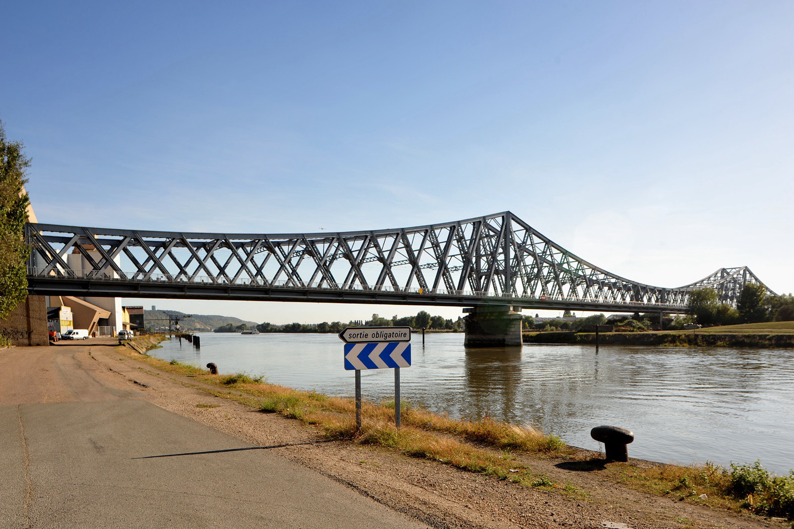
The bridge was built in 1913, and it is a Double-intersection Warren truss railway bridge spanning 169 metres. Here, you can see the X-shape diagonal braces of the bridge are two Warren trusses intersecting each other.
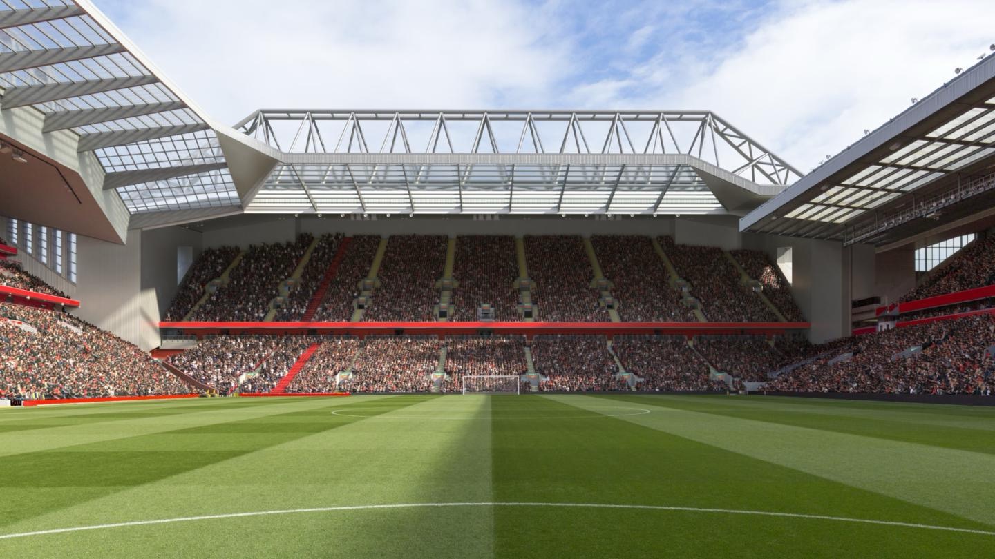
The stadium has the main trusses spanning 145 metres and a depth of 12.5 metres. The 650-tonnes roof trusses were installed using two 1,200 cranes and each member in the truss reach up to 6 metres in length. The truss is a space truss incorporating the Warren truss design.
So which should truss should I choose: Pratt, Howe or Warren?
There is not a simple answer! They each have their advantages and limitations:
- The Pratt and Howe Truss have similar advantages. They have a simple design, are cost-effectiveness and are commonly used in normal practice. They are both easy to build and transport.
- Geometrically, we can see that Warren Trusses use fewer materials than the Pratt and Howe Trusses due to the equilateral triangle pattern. This would lead to a reduced construction time.
- Howe Trusses are better at transferring the load; the compression chords see less force than a Pratt Truss for the same applied load and span, limiting the potential for buckling. See the contours below.
- (However) Pratt Trusses have the advantage of having a shorter compressive member; the verticals in compression are shorter than the diagonals in tension, limiting the potential of buckling.
In the three contours below, the trusses have the same span, applied load and supports. Negative forces are in compression (cooler colours) and positive forces are in tension (warmer colours).


\( \bf{2.4}\) Other Truss Types
Trusses have many variations and shapes, let's explore some more below!
Fink truss
A Fink Truss is commonly used in roofs, especially in homes or pedestrian buildings. It could be seen as a variation of the Warren truss with a W shape in the braces.

King Post truss
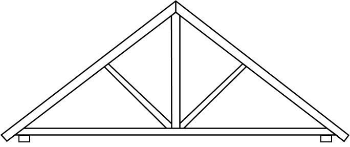
The King Post Truss is normally made from timber, spanning up to 8m. It is commonly used to support the weight of expansive roofs or short span bridges.
Sawtooth (or Butterfly) Truss
This type of truss is typically used for short spans in industrial buildings. It comprises of alternating angled panes of either steep and shallow. The shallow panes are typically orientated to maximise natural light penetration.

K-truss
As the name suggests, the truss is formed by a vertical member and two oblique members in each panel, creating a 'K'. The additional members required in the design can incur additional costs, so K-trusses are rare.
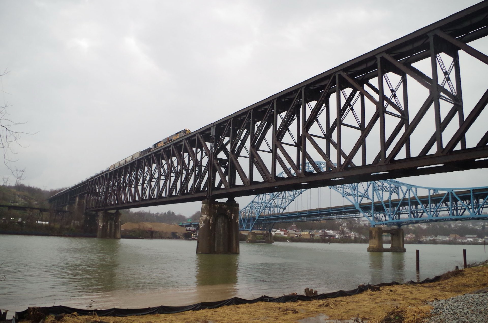
Cantilever truss
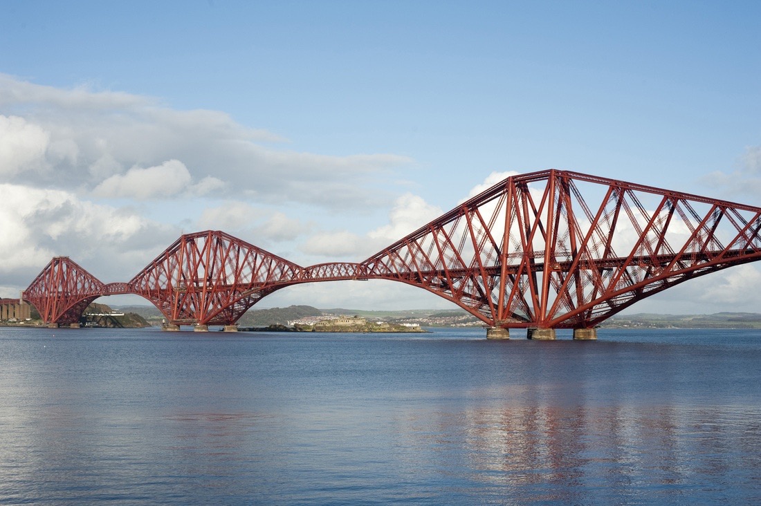
Cantilever bridges are generally made with three spans, where the outer spans are cantilevering. They also typically form an arch shape due to the way their supports meet.
\( \bf{3}\) Truss Analysis
Now that you have a basic understanding of trusses, let's explore how to analyse them! Some assumptions that are considered for truss analysis in an ideal environment:
- Members are subject to axial forces only (shear force and bending moment are neglected, which exist but are nonetheless small)
- Self weight of members may be neglected
- Members assumed to be linear/straight
- Members are connected at joints by frictionless pins
- Applied loads act at joints only
- One end support is idealised as a pin, the other end support is idealised as a roller. This is a useful assumption that simplifies the calculations. As the vertical load is applied, the truss or beam deflects and if one end is a roller this deflection can occur without a change in the total length of the truss. Therefore no extra tension is induced in the truss.
And the general sign conventions for truss analysis is:
- Compression - negative axial force
- Tension - positive axial force
- Members in tension - force acting away from the joint
- Members in compression - forces acting toward the joint
Truss analysis is typically done using an FEA software package on a computer. There is also methods to analyse trusses by hand, called the Method of Joints and Method of Sections. We will look into both methods, but first let's talk about determinacy.
\( \bf{3.1}\) Determinacy
Determining the determinacy of your truss will help you choose which analysis method to use. Generally a perfect truss satisfies:
$$m = 2j - 3$$
Where:
\( \rlap{m} \hspace{2.5em}\): number of members
\( \rlap{j} \hspace{2.5em}\): number of joints
If:
\( \rlap{m < 2j-3} \hspace{5em}\): it is a deficient truss and would collapse
\( \rlap{m > 2j-3} \hspace{5em}\): it is classified as a redundant truss
Statically determinate truss
A structure is said to be statically determinate when the number of unknown forces (reactions and internal forces) can be determined from the equilibrium equations alone, which means it is easy to calculate by hand!
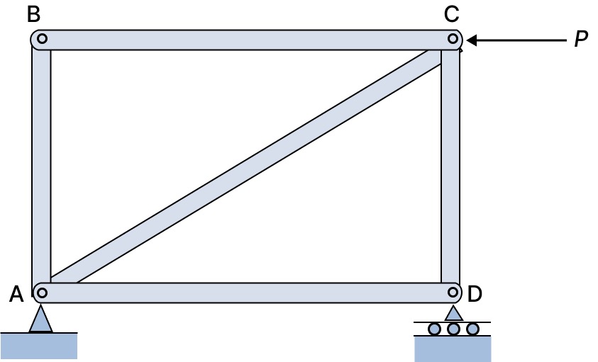
Notice here that there are:
- 5 members
- 4 joints
$$\begin{align*}
m &= 2j - 3 \\
&= 2(4) - 3 \\
&= 5
\end{align*}$$
We will look at analysis of statically determinate trusses further down this design guide, specially at Method of Joints and Method of Sections. You will need the three equilibrium equations:
$$ \sum F_x = 0, \space \sum F_y = 0, \space \sum M = 0 $$
Statically indeterminate truss
On the other hand, statically indeterminate trusses present a challenge since they have unknown forces that can't be resolved solely through the equilibrium equations, and so it is harder to calculate by hand!
How do you analyse them? You can use the:
- Force method - redundant forces are treated as unknowns
- Displacement method - displacements are treated as unknowns
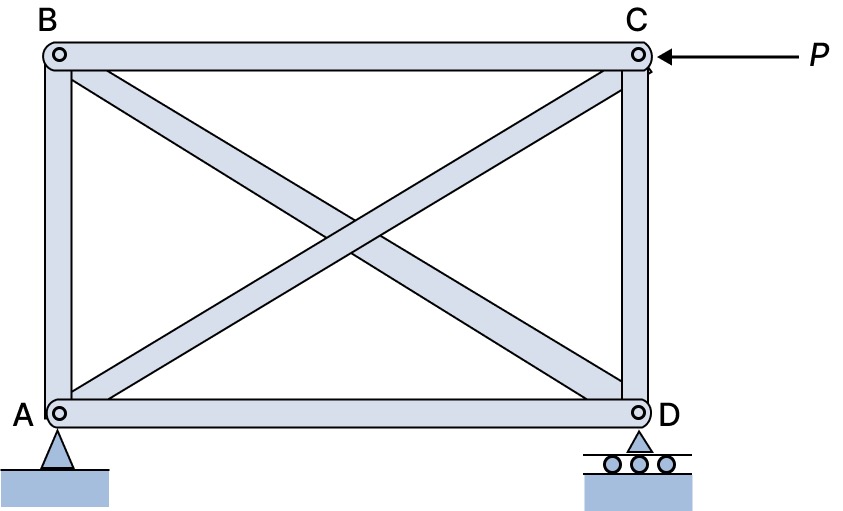
Notice here that there are:
- 6 members
- 4 joints
$$\begin{align*}
m &= 2j - 3 \\
&= 2(4) - 3 \\
&= 5 \neq 6
\end{align*}$$
We will not look at analysis of statically indeterminate trusses in this design guide.
\( \bf{3.2}\) Zero Force Members
Some members actually don't carry any load. You may be thinking, what is their role in the structure? They create a "robust" structure which means the truss won't fail by unexpected loads.
We want to learn how to identify them so we can analyse the rest of the truss by hand quicker!
You can find zero force members at a pin joint not subjected to any external force: see case 1 and case 2.
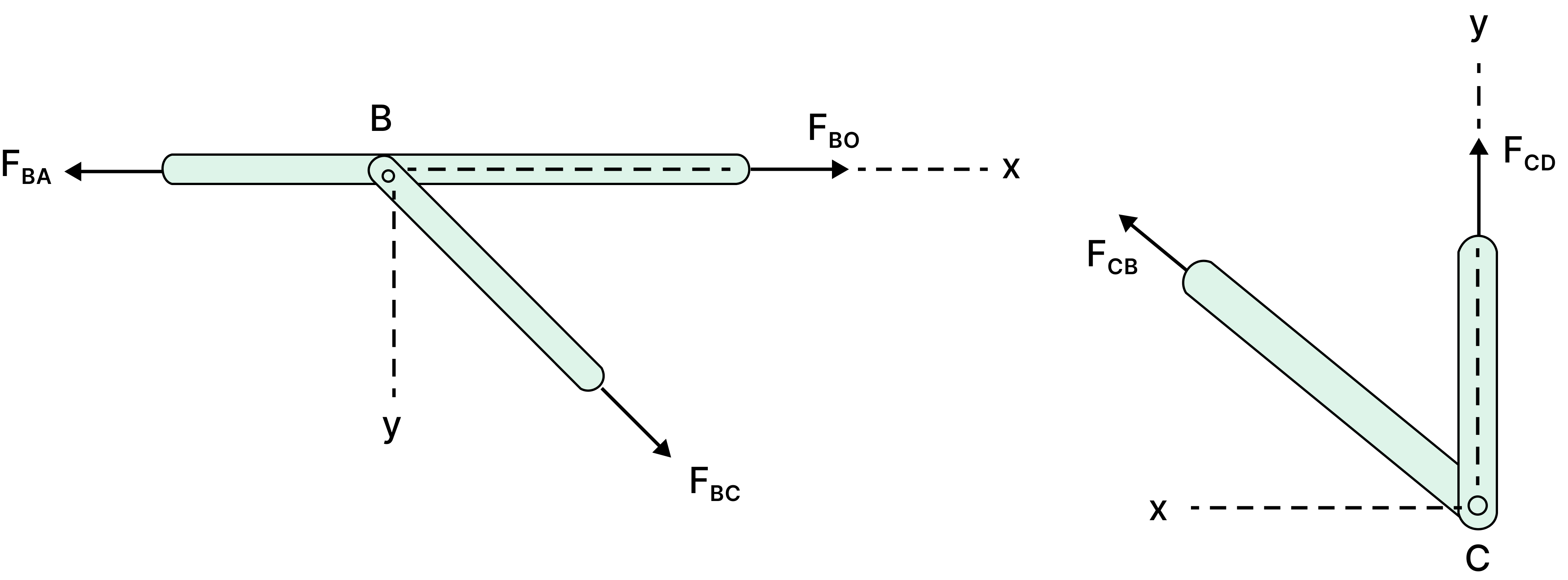
Case 1: If there are three members and two of them are co-linear then the force in the third member is zero. Here, member BC is a zero force member.
Case 2: If there are only two members that are not co-linear, then there is no reaction at the joint and the force in both members is zero. Here, both members CB and CD are zero force members.
A special case where the pin joint is subjected to an external force: see case 3.
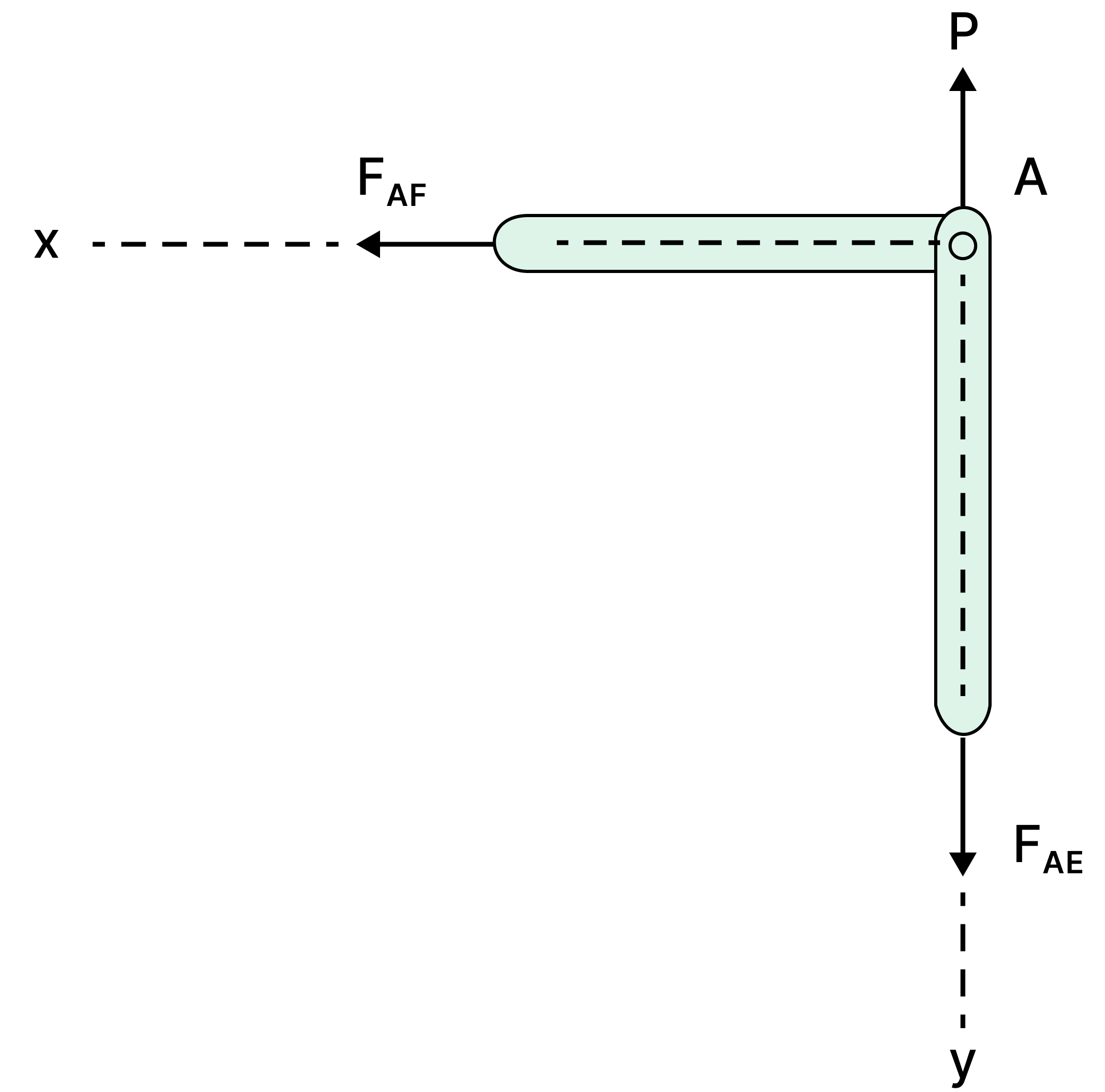
Case 3: If there are two members and an applied force at the pin joint is parallel to one of the members and perpendicular to the other then the force in the member perpendicular to the applied force is zero. Here, member AF is a zero force member.
\( \bf{3.3}\) Method of Joints
This method finds the unknown forces acting on members through the equilibrium of a joint.
General steps:
- Draw a Free Body Diagram (FBD) of the whole truss and solve for the reaction forces at supports using the equilibrium equations
- Draw a FBD of a joint and solve for the internal forces
- Repeat step 2 for all joints
✏️ Worked Example. Let's look at this Pratt truss:
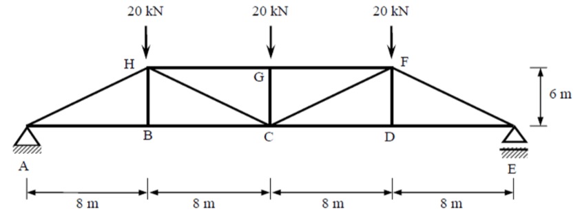
Step 1: Draw a FBD of the entire problem and calculate the reactions at the supports using the three equilibrium equations. You can also use the fact the truss is symmetric to know the vertical reaction forces must be equal!

Step 2: Let's start at the joint where there are the least unknowns. Hint: at the support reactions.
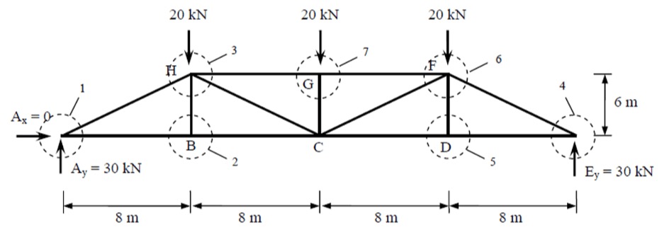
First we make assumptions on the directions of the internal forces (it's okay if your guess ends up being wrong!). At node 1 which is at support A, we can assume that member AH is in compression and member AB is in tension. Using the equilibrium equations we can determine their internal forces:
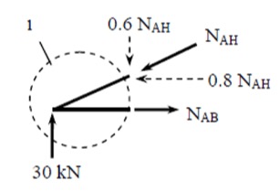
$$\begin{align*}
\sum F_y &= 0 \quad \uparrow (+ve) \\
30 - 0.6N_{AH} &= 0 \\
N_{AH} &= 50 \, \text{kN} \, (C) \\
\\ % Add vertical space
\sum F_x &= 0 \quad \rightarrow (+ve) \\
N_{AB} - 0.8N_{AH} &= 0 \\
N_{AB} &= 40 \, \text{kN} \, (T)
\end{align*}$$
Analyse all the joints sequentially making sure there is a maximum of two unknown forces per joint.
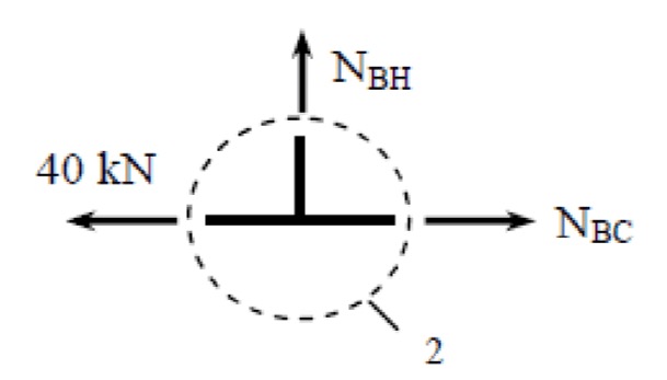
$$\begin{align*}
\sum F_y &= 0 \quad \uparrow (+ve) \\
N_{BH} &= 0
\end{align*}$$
Note, that member BH is a zero force member.
$$\begin{align*}
\sum F_y &= 0 \quad \rightarrow (+ve) \\
N_{BC} - 40 &= 0 \\
N_{BC} &= 40 \, \text{kN} \, (T)
\end{align*}$$
Step 3: And so on!
\( \bf{3.3}\) Method of Sections
This method finds the unknown forces acting on members through the equilibrium of a 'section cut'. The best places to make your cut is through a section with three members (or less), otherwise there will be more unknown forces than there are equilibrium equations to solve. The section could be horizontal, inclined, or vertical.
General steps:
- Draw a Free Body Diagram (FBD) of the whole truss and solve for the reaction forces at supports using the equilibrium equations
- Draw a FBD of a 'section cut' and solve for the internal member forces
- Repeat step 2 until all members are solved
✏️ Worked Example. Let's look at the same Pratt truss from the previous example.
Step 1: Draw a FBD of the entire problem and calculate the reactions at the supports using the three equilibrium equations.

Identify the section(s) where the member forces are required.
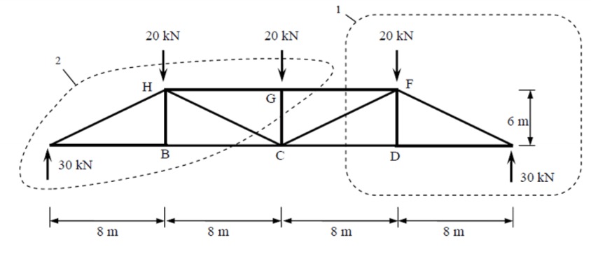
Step 2: Create a FBD of the 'section cut'. Make sure each sections does not contain more than three unknown member forces.
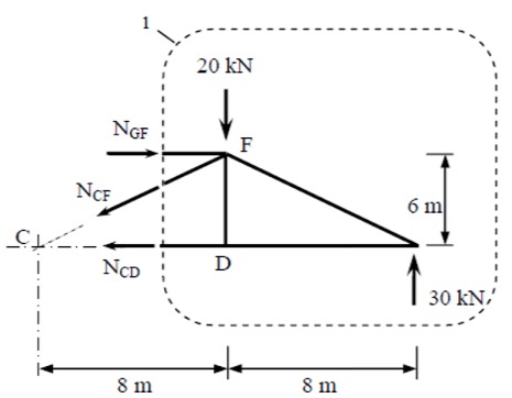
Taking the moments about F:
$$\begin{align*}
\sum M_F &= 0 \quad \circlearrowright (+ve) \\
30 \cdot 8 - N_{CD} \cdot 6 &= 0 \\
N_{CD} &= 40 \, \text{kN} \, (T)
\end{align*}$$
Taking the moments about C:
$$\begin{align*}
\sum M_F &= 0 \quad \circlearrowright (+ve) \\
30 \cdot 16 - 20 \cdot 8 - N_{GF} \cdot 6 &= 0 \\
N_{GF} &= 40 \, \text{kN} \, (C)
\end{align*}$$
Equilibrium of forces in the y-direction:
$$\begin{align*}
\sum F_y &= 0 \quad \uparrow (+ve) \\
30 - 20 - 0.6 \cdot N_{CF} &= 0 \\
N_{CF} &= 16.67 \, \text{kN} \, (C)
\end{align*}$$
Step 3: And so on!
\( \bf{4}\) Steps for Designing Truss Members to Australian Standards
This design guide follows AS/NZS 4100:2020 Steel Structures and AS/NZS 1720:2010 Timber Structures.
Step 1. Select an Appropriate Truss Type
To start, identify the loading conditions imposed on the structure. This could include:
- Dead loads
- Live loads
- Wind loads
- Seismic loads
- Temperature effects etc.
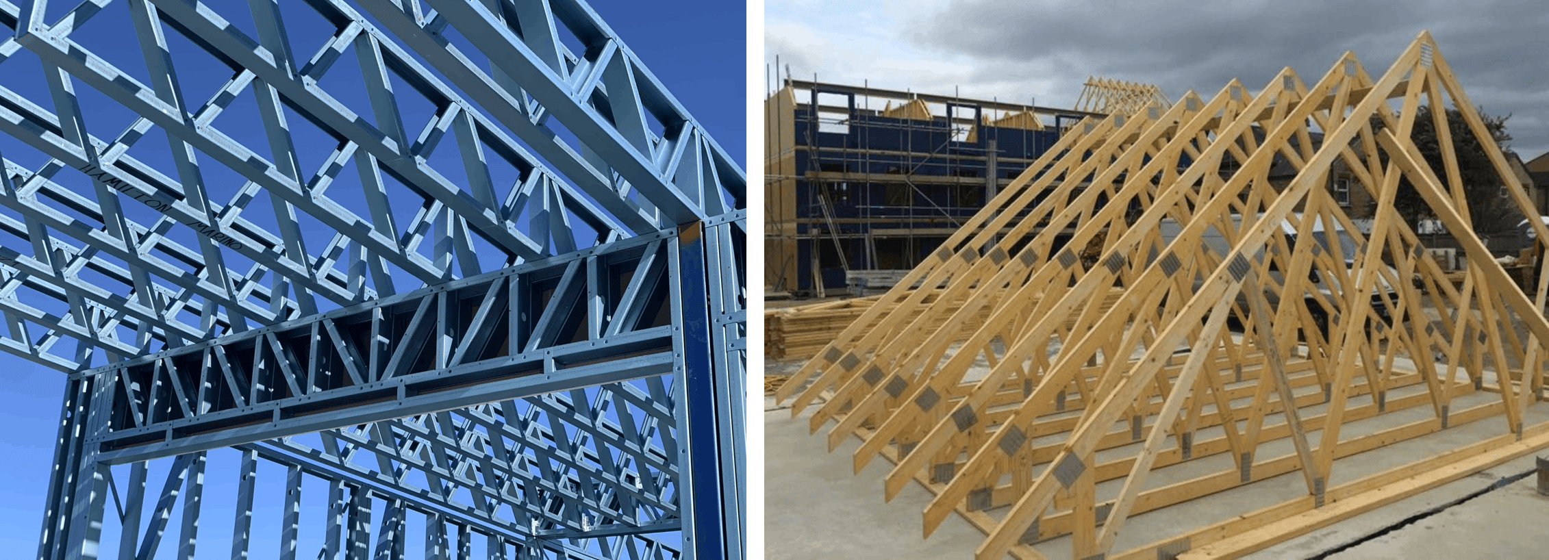
Select the appropriate truss based on the application and loading conditions. Check out some of the common truss types in section 2 of this design guide. Depending on the intended application, trusses are generally made from timber or steel. Applications for truss roof design in residential construction usually involve timber.
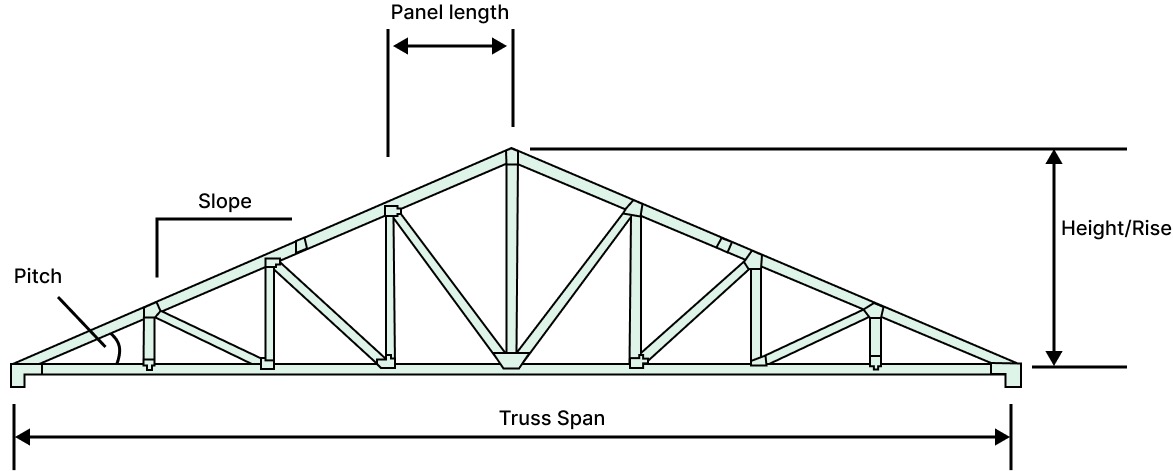
An important rule of thumb used when sizing trusses is the span/height ratio. This ratio indicates the slenderness of the overall truss. Generally, for efficient structural performance the span/height ratio should be within the range 10-15.
Step 2. Calculate Design Loads and Design Actions
Design Loads:
Calculate the design loads in accordance with AS/NZS 1170.1 and AS/NZS 1170.2 and use AS/NZS 1170.0 to determine your combination of actions (ULS and SLS).
For roof truss structures you will need to consider roof covering (e.g. tiles, metal sheeting) and the ceiling (e.g. plasterboard, suspended ceiling systems) for your superimposed dead load.
Check out our Structural Load Calculations design guide for more information.
Design Actions:
Then, determine the resulting forces in the truss members. The two commonly used methods for truss analysis for statically determinant trusses are:
- Method of Joints - considers the equilibrium of a joint
- Method of Sections - considers the equilibrium of a section
Statically indeterminant structures would require solving by:
- Force method - redundant forces are treated as unknowns
- Displacement method - displacements are treated as unknowns
- Finite Element Analysis (FEA) - by hand or using a computer software (e.g. Microstran, Stand7 and SpaceGass)
Step 3. Select a Truss Member Section
Select sections for the first design reiteration of the truss members. Here are some relevant catalogues to get you started:

- Timber sections: Wood Products Victoria: Structural Timber Product Guide
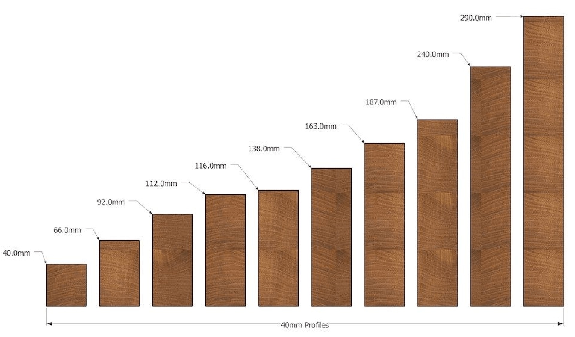
Steel trusses are typically made from hollow sections and/or angle sections for the diagonal members. Timber trusses are typically made from square or rectangular sections.
Step 4. Design the Truss Members
Since we know what design actions each of our truss members see, we know which we need to check for axial tension and which we need to check for axial compression.
For timber design, AS 1720.1:2010:
- Tension members: Clause 4.3
- Compression members: Clause 2.4
Check out our Timber Design to AS1720 design guide.
For steel design, AS 4100:2020:
- Tension members: Clause 7.2
- Compression members: Clause 6.3
Check out our Standard Steel Section Designer to AS4100.
Step 5. Design Connections
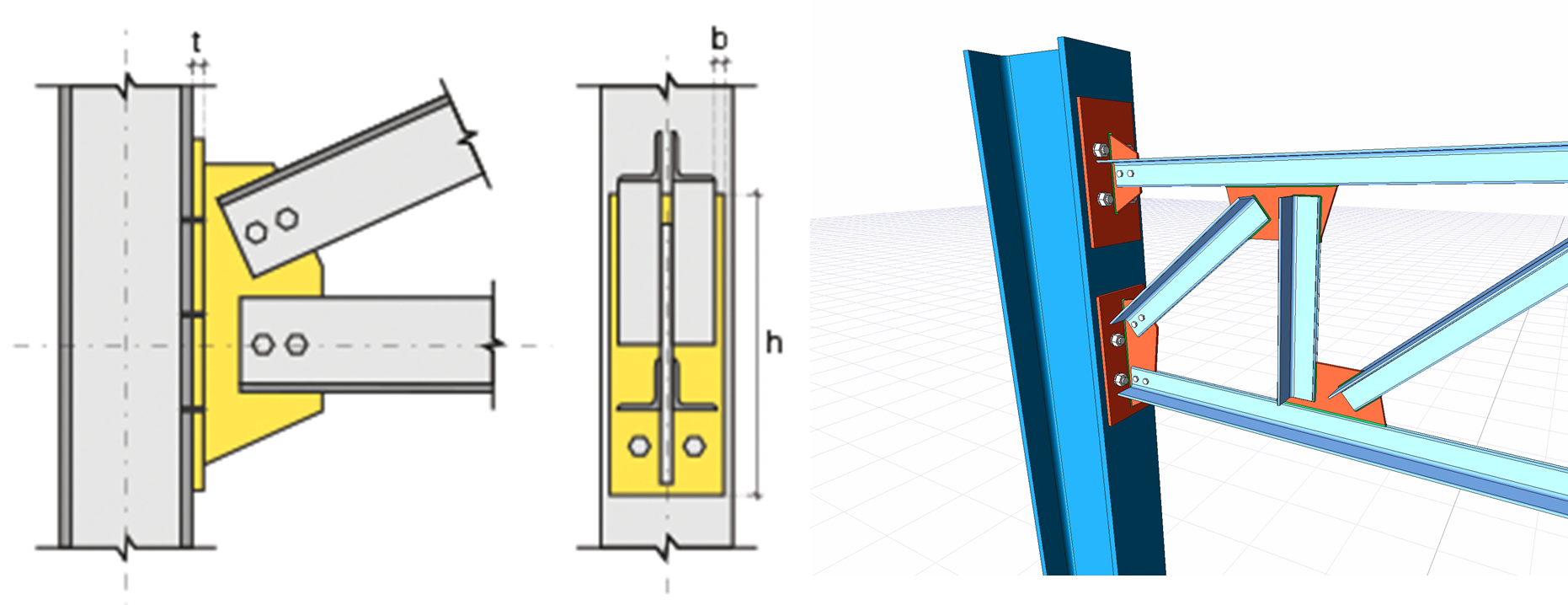
Truss connections at nodes/joints are usually plated bolt connections or plated nailed connections. The requirements for connections are outlined in:
- AS 1720.1:2010: Section 4 - Design Capacity of Joints in Timber Structures
- AS 4100:2020: Sections 9 - Connections
Let's compare bolts vs nails for connections:
- Diameter of fasteners: nail connections are smaller and more flexible, whereas bolt connections are larger and more rigid
- Number of fasteners: nail connections have more fasteners so a low load per unit area, whereas bolt connections have fewer fasteners so a higher load per unit area
- Area of fasteners: nail connections are nailed over a larger area so less stress concentration, whereas bolt connections are bolted over a smaller area so higher stress concentration
- Impact on timber: nails part timber fibres so there is no discontinuity within the fibres, whereas holes are drilled for the bolts and can damage wood fibres
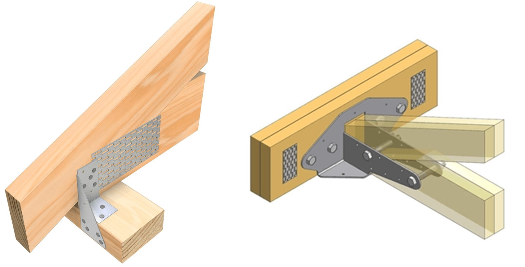
Right: bolted connection for timber roof truss (Image: Pryda)
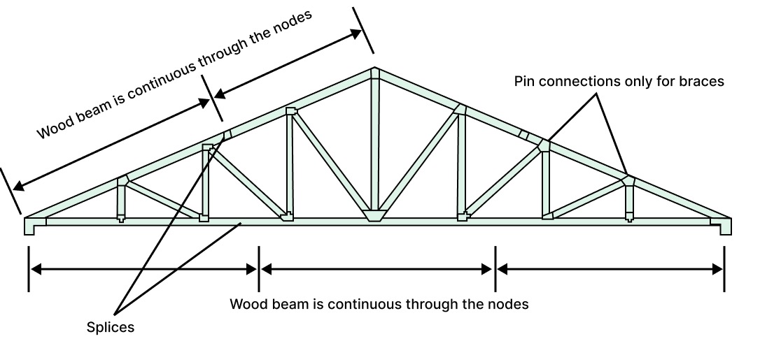
In practice, the top chord and bottom chord may not be connected at the nodes!
For example, wood beams are usually manufactured with fixed dimensions. So, the top and bottom chords usually need longer wood beams. It is best practice to pass the chords through the nodes and splice the members somewhere in the middle third of the member.

Right: steel flange plate splice joint (image: Md Abu Zaed Khan)
