Engineers often find it challenging to extract relevant information from design standards, resulting in wasted time. This article explains Australian Standards AS1648 and AS1720 for residential and general structural timber structures. It covers essential equations, key calculation methods, and design parameters, addressing key shortcomings in the.
Introduction
A common problem faced by engineers when designing structures is identifying relevant information from standards and applying them to their projects. Each design standard contains a vast amount of information; therefore, time and resources may be wasted in searching and selecting bits that are useful for design. This article aims to aid engineers in such a situation by providing a guideline on the design procedure of timber structures according to the Australian Standards, namely AS1648 (residential timber code), and AS1720 (general structural timber code). Fundamental equations, calculation methods for different timber materials, and important design parameters are explained in the following sections. Ultimate strength and serviceability limit state designs are extensively discussed, and any shortfalls in the standards that need improvement are pointed out.
Guidelines for the manufacture of timber materials
Australian Standards also present guidelines to be followed during the manufacture of timber materials. These documents set standardized testing and grading methods and outline minimum requirements for material properties (such as moisture content, modulus of elasticity, etc.). All timber materials manufactured in Australia must satisfy conditions outlined in the standards and be appropriately graded before they apply to the actual design of timber structures:
- AS 2082/2858 - Visually graded sawn timber
- AS/NZS 1748 - Mechanically graded timber
- AS 3519 - Proof-graded timber
- AS/NZS 2269 - Structural plywood
- AS/NZS 4357 - Structural laminated veneer lumber
- AS/NZS 1328.1 - Glued laminated timber
- AS 3818.3/3818.11 - Round timber
\( 1 \) Timber Properties
Australian Standards set out guidelines and minimum requirements for material properties, design parameters, design procedures and calculation methods. Here, we explain some pertinent timber properties that should be considered carefully when undertaking timber design calculations.
\( 1.1 \) Seasoning
Harvested trees typically contain a lot of water. Once trees are cut and sawn, even more moisture is lost at a highly variable rate. Seasoning is the process of drying timber and removing moisture from the material at a uniform rate by exposing it to circulating air and controlled heat:
- Seasoned Timber: refers to timbers whose moisture has been dried out through a seasoning process. The moisture content of seasoned timbers typically varies between 10-15%. The process of seasoning can enhance the basic characteristic properties and dimensional stability of timber, increasing stiffness, bending and compression strength. Limiting moisture content to no more than 15%, as per seasoning recommendations in Australian Standards, allows timbers to have satisfactory performance with respect to appearance and stability.
- Unseasoned Timber: refers to timbers not far enough along the drying process to be considered seasoned, and its moisture content varies anywhere between 25-100%. Moisture content should be an essential consideration in design as it can affect the outcome of a project. Given that unseasoned timber has a lot more moisture, a frame or building of unseasoned timber will be able to expand, contract and settle onto its weight, adapting to environmental conditions around it better than seasoned timber. If environmental conditions are an important factor in your project, consider unseasoned timbers, as they can settle into different environmental conditions without compromising structural integrity.
\( 1.2 \) Types
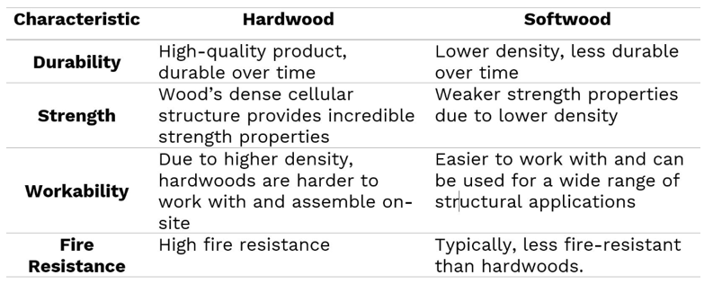
Wood from trees is typically classified as either hardwood or softwood. You can be forgiven for thinking that hardwood indicates the relative hardness of the wood, but this is often misleading as many hardwoods are relatively soft and vice versa. The the main characteristic differences between hardwoods and softwoods are shown below.
\( 1.3 \) Stress Grade
Structural timber is typically sold and distributed as a stress-graded product. Timbers used in structural applications are assigned a stress grade classification. These grades can be obtained from visual or machine grading. The grading specifies structural timbers' characteristic values of strength and stiffness and stress limits. Stress grades are generally known by either:
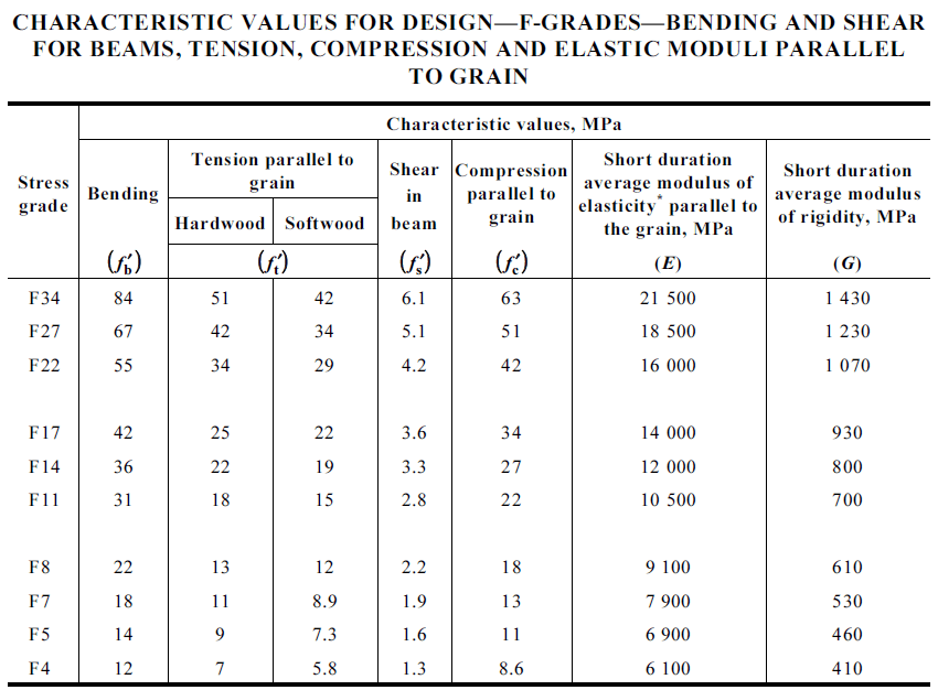
- F-Grades: F4 - F34 (i.e. F22 indicates that the bending stress timber is approximately 22 MPa, and it can withstand that force without excessive deflection). Most Hardwoods are ‘F’ graded, with the higher the grade, the stronger the timber. F-Grades for sawn timbers are given in Table H2.1 of Appendix H in AS1720.1, and F-grades for plywood as given in Table 5.1.
- Machine-graded pine (MGP): MGP10 - MGP15 (Structural pine is a plantation species that are generally graded by a machine that bends a wooden member with a set amount of force, measuring deflection. This sets the grading scale for MGP timbers). MGP grades and properties for sawn timber as given in Table H3.1 of Appendix H.
- Australian Ash (A17-grade): A-grades apply to a visually graded mixture of seasoned alpine ash and mountain ash. A17 grades and properties for sawn timber are given in Table H3.1 of Appendix H in AS1720.1.
- Glue-Laminated Timber (GLT): GLT are engineered timbers whose stress grades and properties are as given in Table 7.1 in AS1720.1 or as detailed in a manufacturer's product specification.
It is useful to know what a specific stress grade of timber means for your design. For example, if you require a beam that needs to span a longer distance with no intermediate supports, it would be logical that an F27 timber beam would be able to span further than an F17 beam of the same size without deflecting too much or breaking. In another scenario, you may choose a smaller piece of an F27-graded timber to perform as adequately as a smaller, weaker F17 beam.
\( 2 \) Ultimate Strength Limit State (ULS)
AS1684 and AS1720 provide detailed, comprehensive guidelines for ULS design. The calculation methods for design bending moment, shear, and bearing capacities of structural timber members, joints, and fasteners are robust enough to account for different scenarios and environmental factors. According to AS1720 Clause 2.1.2 and 2.1.3, the design capacities of members and joints must satisfy the following limit:
$$R_d>R^*$$
where:
\(\rlap{R_d} \hspace{2.5em}\) : design capacity
\(\rlap{R^*} \hspace{2.5em}\) : imposed design action
Explore the following subsections to read more about the ULS design parameters.
\( 2.1 \) Design Capacity \(R_d\) and Design Action \(R^∗\)
Design capacities for all structural timbers are obtained by modifying characteristic capacities with factors appropriate to service conditions and material property type. This process applies to all types of timber.
(R_d) is the design capacity of the timber member/joint, or the maximum amount of load that a particular element can take before failure. It is the product of the characteristic value of the material, the appropriate geometric property, modification factors and a capacity factor. (R_d) must be larger than (R^*\), the design action, or the maximum load that the element is expected to experience during its usage.
$$\begin{align} & R_d=\phi k_{mod}f'_oX \hspace{2.5em} \vphantom{\frac{\frac{0}{0}}{\frac{0}{0}}} &&\text{for timber members }\\ & R_d=\phi k_{mod}nQ \hspace{2.5em}\ \vphantom{\frac{\frac{0}{0}}{\frac{0}{0}}} &&\text{for timber joints} \end{align}$$
where:
\(\rlap{\phi} \hspace{2.5em}\) : capacity reduction factor (AS1720.1 Clause 2.4)
\(\rlap{k_{mod}}\hspace{2.5em}\) : product of modification factors (AS1720 Clause 2.4)
\(\rlap{f'_o} \hspace{2.5em}\) : characteristic value of material design strength
\(\rlap{X} \hspace{2.5em}\) : geometric section property of member
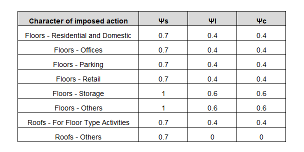
The design action \( R^* \) is calculated following load combinations outlined in AS1170, which accounts for different types of loads acting on the structure, such as wind, snow, live (or imposed) and dead loads. For live loads, like foot traffic and storage, the load is multiplied by a factor in the load combination.
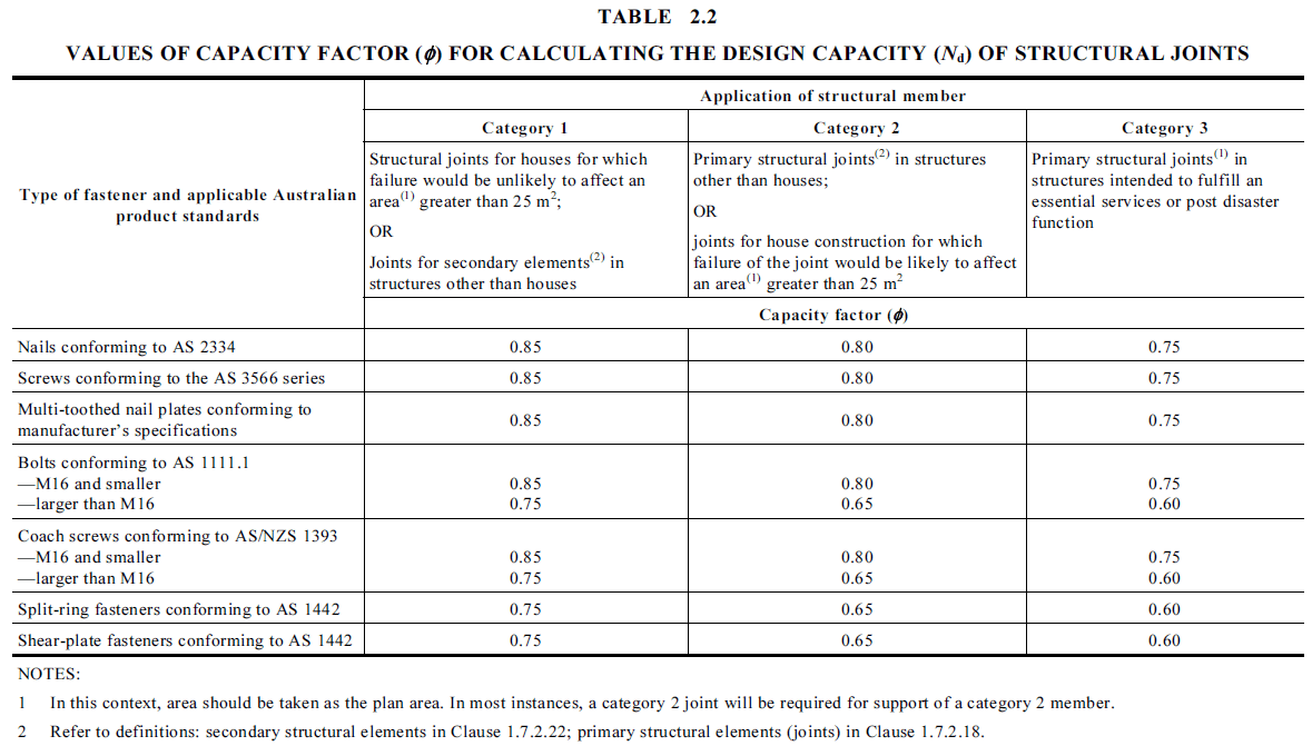
\( 2.2 \) Capacity Factor \( \phi \)
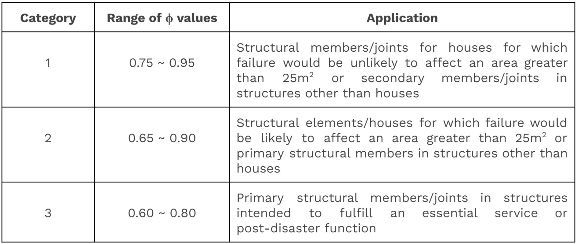
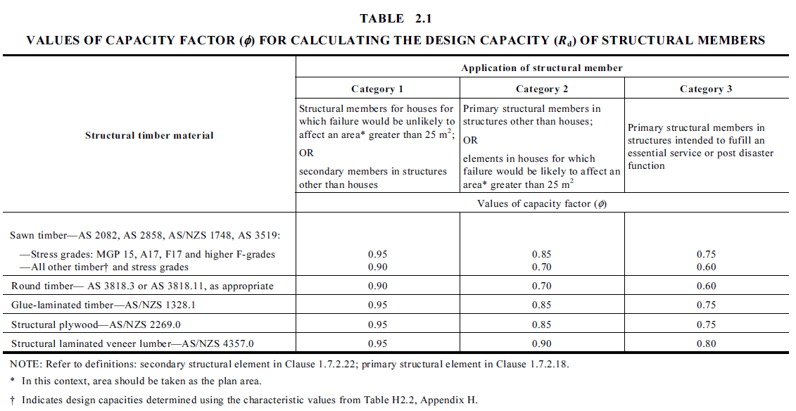
Capacity factors are used to reduce the design capacity of structural elements. In AS1684 and AS1720, the \(\phi\) values for timber members/joints are selected based on their application and material type. Higher values are used for structural elements deemed to cause less danger upon failure.
List of all modification factors:
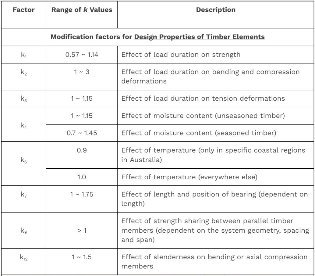
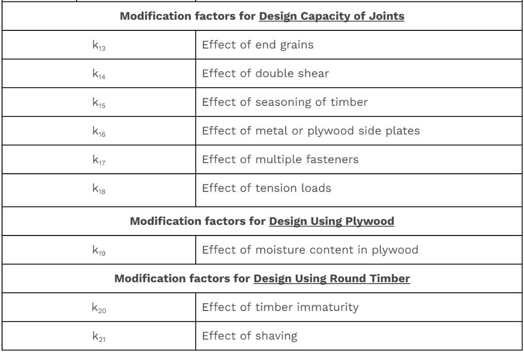
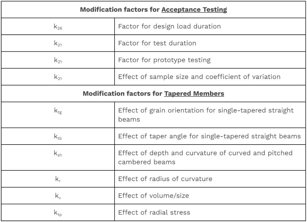
Explore below for details about the commonly used modification factors:
\( 2.2.1 \) Load duration factor, k1
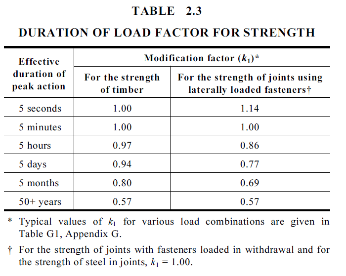
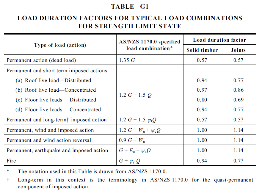
As per AS1720.1 Clause 2.4.1, the modification factor k1 describes the effect of duration of load on strength. For any given combination of loads of differing duration, k1 is the one appropriate to the action with the shortest duration.
\( 2.2.2 \) Moisture content factor, k4
As per AS1720.1 Clause 2.4.2, k4 considers the effect of seasoning and moisture content. For seasoned timber, k4 generally equals 1. When seasoned timber is subjected to an environment in which its average moisture content exceeds 15%, its capacity is reduced. In such cases, k4 can be calculate as the greater of:
$$k_4 = 1- 0.3\left(\frac{EMC - 15}{10}\right)\space\space \text{or}\space0.7$$
where:
\(EMC\): highest annual average moisture content in timber (%)
For unseasoned timber, k4 also generally equals 1. However, if unseasoned timber is used under normal temperature and humidity conditions and will not be subjected to its full design load until it has partially seasoned (i.e. reaches below 25% moisture content), its capacity can be increased.

\( 2.2.3 \) Temperature factor, k6
As per AS1720.1 Clause 2.4.3, k6 considers the effect of temperature. For timber structures that are covered and under ambient conditions, k6 equals 1. For seasoned timber structures in coastal regions of Queensland north of latitude 25S and all other regions of Australia north of latitude 16S, k6 shall be taken as 0.9.
\( 2.2.4 \) Bearing factor, k7
k7 considers the effect of rectangular bearing areas. Where the timber member is located 75mm or more from the end of a piece of timber, bearing strength perpendicular to the grain can be increased. The length of bearing is measured parallel to the grain of the supported member.


\( 2.2.5 \) Load sharing factor, k9
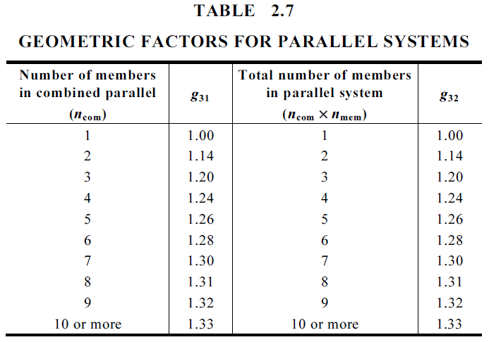
As per AS1720.1 Clause 3.4.2, k9 considers the effect of parallel timber members acting together as a combined, strength-sharing structural system. Parallel acting systems are classified as either combined systems or discrete systems. A combined parallel system consists of two or more elements that are effectively fastened together, where as a discrete parallel system has three or more members that are discretely spaced parallel to each other. These discrete members support the same set of overlying members or a structural sheathing material.

For rectangular sawn and round timbers, k9 is a function of the number of members in the system, and can be calculated using AS1720.1 Eq. 2.4.5.3 and Table 2.7. For plywood, GLT and LVL, k9 should be taken as 1.
$$k_9 = g_{31} + (g_{32} - g_{31})\left( 1 - \frac{2s}{L} \right) \ge 1.0$$
\( 2.2.6 \) Stability factor, k12
k12 considers the stability of the member, but varies when considering bending or compression.
For bending, as per AS1720.1 Clause 3.2.4, k12 considers the effect of lateral and torsional restraints and member slenderness. The spacing of the lateral and torsional restraints govern how the member buckles under load, which affects its capacity. The slenderness factor, S1, is calculated differently depending on how the member is restrained:
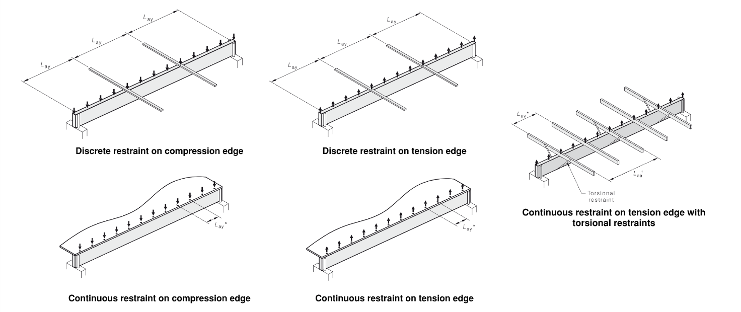
$$$$\begin{aligned}&S_1 = 1.25\frac{d}{b}\left({\frac{L_{ay}}{d}}\right)^{0.5}\vphantom{\frac{\frac{0}{0}}{\frac{0}{0}}} &&\text{Discrete restraint on compression edge} \\&S_1 = \left(\frac{d}{b}\right)^{1.35}\left(\frac{L_{ay}}{d}\right)^{0.25}\vphantom{\frac{\frac{0}{0}}{\frac{0}{0}}} &&\text{Discrete restraint on tension edge} \\&S_1 = 0 \vphantom{\frac{\frac{0}{0}}{\frac{0}{0}}} &&\text{Continuous restraint on compression edge} \\&S_1 = 2.25\frac{d}{b} \vphantom{\frac{\frac{0}{0}}{\frac{0}{0}}} &&\text{Continuous restraint on tension edge} \\&S_1 = 1.5\frac{d}{b}\space\div\space \left((\frac{\pi d}{L_{a\phi}})^2 + 0.4\right)^{0.5} \vphantom{\frac{\frac{0}{0}}{\frac{0}{0}}} &&\text{Continuous + torsional restraint on tension edge} \end{aligned}$$$$
where:
\(\rlap{d} \hspace{1.5em}\) : Depth
\(\rlap{b} \hspace{1.5em}\) : Width
\(\rlap{L_a} \hspace{1.5em}\) : restraint spacing
For compression, as per As per AS1720.1 Clause 3.3.3, k12 considers the effect of buckling restraints and member slenderness. The end restraint has an impact on the slenderness and buckling of the timber column. Better restraints at the supports and along the height of the column provide better resistance against buckling.
$$\begin{align}
& k_{12}=1.0 \vphantom{\frac{0}{0}} && \text{for } \rho_ cS\le10\\
& k_{12}=1.5-0.05 \rho_ cS \vphantom{\frac{0}{0}}&& \text{for } 10 \le \rho_c S \le 20 \\
& k_{12}=\frac{200}{(\rho_ cS)^2} && \text{for } \rho_ cS\ge 20\end{align}$$
where:
\(\rlap{ S = S_3 } \hspace{3.5em}\) : for buckling about the major axis
\(\rlap{ S = S_4 } \hspace{3.5em}\) : for buckling about the minor axis
For buckling about the (major) X-axis, \( S_3 = min(\frac{L{ax}}{d},\frac{g_{13}L}{d}) \)and for buckling about the (minor) Y-axis, \( S_4 = min(\frac{L_{ay}}{b},\frac {g_{13}L}{b}) \).
\( 2.3 \) Characteristic Capacity \( f'_o \)
Every grade and species of Timber has its own characteristic properties that do not change regardless of design conditions. Characteristic properties or values are defined by the Standards or manufacturer’s data. Characteristic strength properties are usually denoted by single primes (’) and can include some of the following:
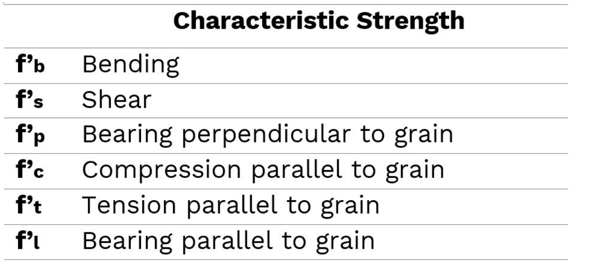
The value f’o is the characteristic capacity for the relevant design action in question (bending, tension, compression, shear, etc.). For example, when designing for bending moment capacity, f’o = f’b (characteristic value in bending for the section size) and X = Z (section modulus of the beam about the bending axis).

Characteristic material strength is defined as the strength below which no more than 5% of the results are expected to fall, as assessed by a standardized test. When timber is manufactured, it undergoes tests, and grades are allocated according to the results. In Australian standards, timber is graded by its strength in shear, bending and tension, and compression parallel to the grain.
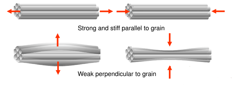
A unique property of timber is that strength varies depending on the direction of the applied load. Due to the cellular structure of wood, engineered wood products are stronger when loaded parallel to the grain compared to perpendicular. AS1720 Section 3 accounts for this phenomenon through the provision of design tension, compression, and torsion capacity formulae in both directions.
\( 2.4 \) Geometric properties \( X \)
The geometric section property of a member used in the capacity equations \( R_d \) is relevant to the action being considered.
The geometric properties in compression and tension members are:
\(\rlap{ A_c } \hspace{3.5em}\) : gross cross-sectional area
\(\rlap{ A_t } \hspace{3.5em}\) : net cross-sectional area of tension member
\(\rlap{ A_{tp} } \hspace{3.5em}\) : member width multiplied by effective length
\( \hspace{3.5em}\) stressed in tension for tension perpendicular to grain
The geometric properties in bending members used for bending, shear and bearing capacities include:

\( 2.5 \) Geometric properties \( N_{d,c} \)
Permissible allowable stress limits or design limit capacities of timber columns are then calculated for each check by multiplying the relevant characteristic properties, modification factors and geometric properties together:
Compressive capacity parallel to grain, \( N_{d,c}=\phi k_1k_4k_6k_{12}f'_cA_c \)
Compressive capacity perpendicular to grain, \( N_{d,t}=\phi k_1k_4k_6f'_tA_t \)
Tensile capacity perpendicular to grain, \( N_{d,tp}=\phi k_1k_{11}f'_{tp}A_{tp} \)
$$\begin{align}
& N_{d,c}=\phi k_1k_4k_6k_{12}f'_cA_c \vphantom{\frac{0}{0}} && \text{Compressive capacity parallel to grain } \\
& N_{d,t}=\phi k_1k_4k_6f'_tA_t \vphantom{\frac{0}{0}} && \text{Compressive capacity perpendicular to grain } \\
& N_{d,tp}=\phi k_1k_{11}f'_{tp}A_{tp} \vphantom{\frac{0}{0}} && \text{Tensile capacity perpendicular to grain } \end{align}$$
The modification factors most relevant for compressive strength and tension member design are shown below:
\(\rlap{ k_1 } \hspace{1.5em}\) : load duration factor (AS1720.1 Clause 2.4.1)
\(\rlap{ k_4 } \hspace{1.5em}\) : seasoning factor (AS1720.1 Clause 2.4.2)
\(\rlap{ k_6 } \hspace{1.5em}\) : temperature factor (AS1720.1 Clause 2.4.3)
\(\rlap{ k_9 } \hspace{1.5em}\) : volume factor (AS1720.1 Clause 3.4.2)
\(\rlap{ k_{12} } \hspace{1.5em}\) : stability factor (AS1720.1 Clause 3.3.3)
\( 2.6 \) Bearing Capacity \( N_{d,p} \)
As per As1720.1 Clause 3.2.6.1, the design capacity in bearing perpendicular to the grain is:
$$N_{d,p}=\phi k_1k_4k_6k_7f'_pA_p$$
where:
\(\rlap{ A_p } \hspace{1.5em}\) : bearing area for loading perpendicular to grain
\(\rlap{ f'_p } \hspace{1.5em}\) : characteristic value in bearing perpendicular to grain
\( 3 \) Serviceability Limit State (SLS)
The major shortfall in AS1684 and AS1720 is the lack of comprehensive consideration for deflection and vibration control. Timber is lighter and proportionally less stiff compared to reinforced concrete and steel; hence, it is extremely prone to deflections and vibrations when subject to similar load patterns. Timber’s lighter weight leads to oscillations that can cause discomfort to occupants, and lower stiffness leads to larger deflections. Additionally, timber is an environment-sensitive material that is heavily influenced by temperature and moisture content in the atmosphere. Therefore, timber structures must be constructed to ensure satisfactory performance and safety throughout their service life, accounting for variance in material properties over time. In fact, serviceability is often the governing limit state for timber elements rather than ultimate strength.
Explore the toggles below to read about two of the SLS design criteria.
\( 3.1 \) Deflection
For the calculation of deflections, AS1720 suggests the use of upper-bound estimates obtained through elastic analysis methods. The upper-bound deflection limit is found using the lower 5th percentile estimate elasticity of modulus, \(E_{0.05}\) (generally, a range of E values are attained whilst grading through tensile tests). In cases where this information may be unavailable, the standard recommends calculating it as a proportion of the average value of the modulus of elasticity:
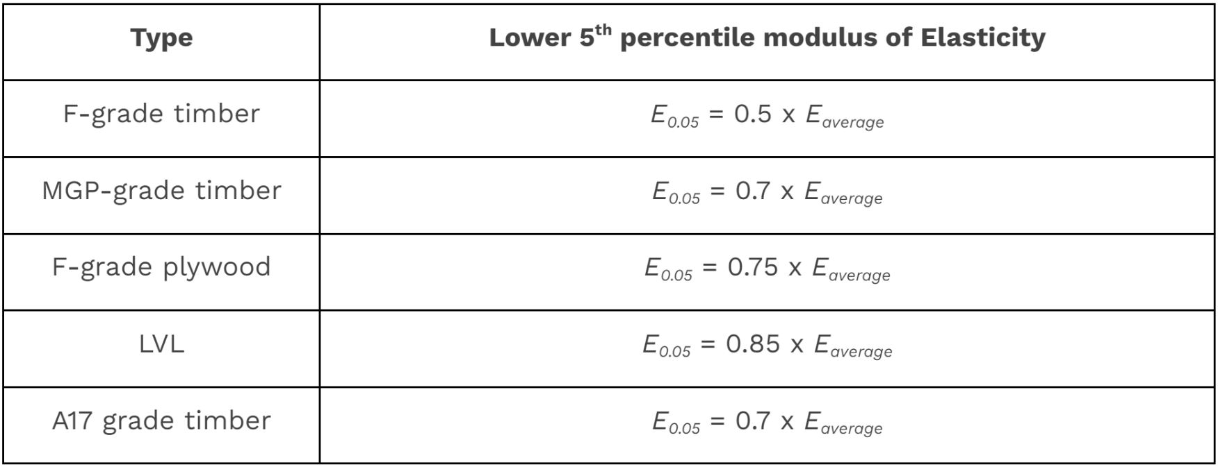
While these estimates may be useful for smaller projects like residential complexes, they are not appropriate for large-mass timber structures. Upper-bound estimates tend to greatly under-estimate the limits, and engineers may design conservatively, leading to unnecessarily thicker and stronger elements. This can result in dramatically increased cost and time demands on a project.…even more than usual!
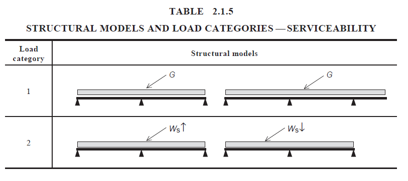
In contrast, AS1684 provides tables with “structural models” that are used to determine span-relative deflection limits. The structural models are categorized according to the load type (e.g. distributed or concentrated, live or permanent, etc.), and then modification factors and deflection limits are selected based on the load category. Section 2 of AS1684.1 covers deflection limits for the design of timber roof members in residential buildings, which includes roof battens, rafters, underpurlins, strutting beams, ceiling battens, and joints, as well as hanging, counter, and verandah beams. An example of structural models and load categories for serviceability design from AS1684 Clause 2.1.3.2 is shown below:
\( 3.2 \) Vibration
Vibration control measures are covered briefly in AS1684 and AS1720. Vibrations induced by machinery and human activities (walking, running, dancing, etc.) cause the structure to sway and oscillate, which may be fatal if the frequency of this oscillation matches the natural frequency of the structure. The standards state that ‘the dynamic response of floor systems, including frequency of vibration, should be considered…’ but no equations or guidelines are provided.
