Learn how to calculate the flexural and shear design capacities for a concrete beam, according to AS3600-2018.
Introduction
Beams are an important structural element in reinforced concrete (RC) structures. They are designed to provide resistance to external loads that cause shear forces, bending moments and, in some cases, torsion across their length.
Concrete is strong in compression but weak in tension, so reinforcement is added to take the tensile stresses induced when beams are loaded. In a sagging beam the tensile stresses are along the bottom of the beam, so theoretically, no top reinforcement is required. However most beams will still have top reinforcement for constructability reasons, so that the ligs can hang from the top bars.

Right: shear reinforcement (also referred to as 'ligs', 'links' or 'fitments')
The latest Australian Standard for concrete structures, AS3600-2018, has undergone significant updates and changes since the 2009 edition, mainly concerning:
- Rectangular stress-block configuration (Section 8.1.3)
- Values of the capacity reduction factor Φ, for different action effects (Table 2.2.2)
- Shear and torsion design (Section 8.2)
Generally, the limit state checks for RC beams include the flexural, shear, deflection and crack control. This design guide covers the first two checks: flexural and shear capacity.
\( \bf{1} \) Ultimate Flexural Capacity
\( \bf{1.1} \) Rectangular Stress Block
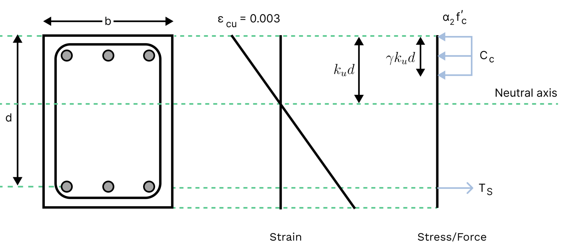
The flexural (also referred to as 'bending' or 'moment') capacity of a beam cross-section is determined using the Rectangular Stress Block method (Cl. 8.1.2). The stress distribution in concrete under bending is curved in reality, however it can be converted to an equivalent rectangular stress block by the use of reduction factors \( \alpha_2 \) and \( \gamma \).

By taking moments about the concrete compression force \( C_c \), we can derive the nominal flexural capacity as:
$$ M_u = A_{st}f_{sy} \times \left(d - \dfrac{\gamma k_ud}{2}\right) $$
The design flexural capacity is given by \( \phi M_u \), where \( \phi \) is the reduction factor as determined from Table 2.2.2.
The \( k_u \) factor is the depth ratio of the neutral axis from the extreme compressive fibre to the bottom reinforcement, at ultimate strength. Therefore \( k_{u}d \) represents the depth to the neutral axis.
The \( k_u \) factor is not defined explicitly in the standards and must be computed via force equilibrium:
$$ \begin{aligned}
C_c & =T_s \vphantom{\frac{\frac{0}{0}}{\frac{0}{0}}} \\
\alpha_{2}f'_c\gamma bd &= A_{st}f_{sy} \vphantom{\frac{\frac{0}{0}}{\frac{0}{0}}} \\
\rightarrow k_u &= \dfrac{A_{st}f_{sy}}{\alpha_{2}f'_c\gamma bd} \vphantom{\frac{\frac{0}{0}}{\frac{0}{0}}} \\
\end{aligned} $$
Where, as per Cl 8.1.3:
\( \rlap{\alpha_2} \hspace{2.5em}=0.85-0.0015f'_c \ge 0.67 \)
\( \rlap{\gamma} \hspace{2.5em}= 0.97-0.0025 f'_c \ge 0.67 \)
\( \bf{1.2} \) Minimum Strength, \( (M_{uo})_{min} \)
The ultimate flexural strength at critical sections should not be less than the minimum required strength in bending \( (M_{uo})_{min} \), given by Eq. 8.1.6.1 (1):
$$ (M_{uo})_{min}=1.2[Z(f'_{ct.f}+P_e/A_g)+P_ee] $$
Where:
\( \rlap{Z} \hspace{2.5em} \): section modulus of theuncracked cross-section
\( \rlap{f'_{ct.f}} \hspace{2.5em} \): characteristic flexural tensilestrength of the concrete
\(\rlap{P_{e} } \hspace{2.5em} \): total effective prestress force allowing forall losses of prestress
\(\rlap{e} \hspace{2.5em} \): eccentricity of the prestressing force
Where there is no pre-stressing, \( (M_{uo})_{min} \) is given by:
$$ (M_{uo})_{min} = 1.2Zf'_{ct.f} $$
Also according to Cl 8.1.6, for reinforced concrete sections, the above requirement is deemed to be satisfied if the total area of the provided tensile reinforcement satisfies the following:
$$ A_{st}\geq [\alpha_b(D/d)^2f'_{ct.f}/f_{sy}]b_wd $$
For rectangular sections, \( \alpha_b=0.2 \).
\( \bf{1.3} \) Ductility
To finalise your ultimate bending capacity limit state, youmust check your section is ductile. A ductile section ensures the reinforcementwill yield before the concrete crushes, which is deemed a less dangerousfailure mechanism since the failure occurs relatively slow compared to a suddenbrittle failure. As per Cl 8.1.5, a section is ductile if:
$$ \begin{gather}
& k_{uo} \le 0.36 \vphantom{\frac{\frac{0}{0}}{\frac{0}{0}}}\\
& k_{uo} = k_u \text{ factor for a section in pure bending} \vphantom{\frac{\frac{0}{0}}{\frac{0}{0}}}\\
\end{gather} $$
\( \bf{2} \) Ultimate Shear Capacity
Section 8.2 outlines methods for calculating strength of beams in shear. We will leave out torsion from this design guide, but it must be checked if the beam sees in-plane rotation.
The total nominal shear capacity of a section \(V_u\) is the combination of the shear strength contributed by concrete \(V_{uc}\), shear reinforcement \(V_{us}\) and the vertical component of prestressing \(P_{v}\), where the sum is limited by \(V_{u.max}\):
$$ \ V_u\ = (V_{uc}+V_{us}+P_v) \le V_{u.max} $$
The design shear capacity is given by \( \phi V_u \),where \( \phi \) is the reduction factor as determined from Table 2.2.2.
In this design guide, we will not consider prestress i.e. \(P_{v}=0\).
\( \bf{2.1} \) Truss Analogy
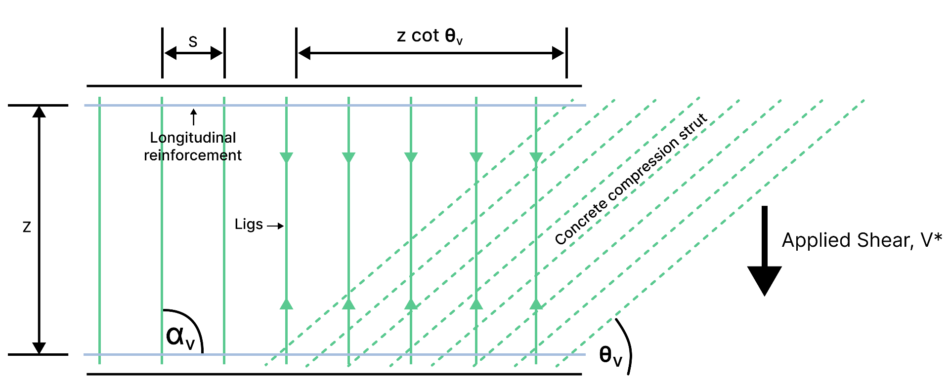
AS3600 (similar to other international codes) use a truss analogy of shear resistance, where the diagonal concrete strut is in compression and the vertical tie (provided by shear reinforcement) is in tension.

The strut angle \( \theta_v \) is a variable parameter that varies with the magnitude of applied load, and affects the distribution of shear resistance:
- a smaller \( \theta_v \) means the strut crosses more shear ligs and therefore a smaller area of shear ligs is needed
- a larger \( \theta_v \) means more of the applied shear force is taken by the vertical tie (shear ligs) and therefore a larger area of shear ligs is needed
It is common practice to ensure \( \theta_v \geq 36 °\) to ensure the required shear reinforcement is not under-conservative.
\( \bf{2.2} \) Shear Reinforcement Requirement
As per Cl 8.2.1.6, shear links are required if either of the following is true:
$$ \begin{gather}
& V^* >\phi(V_{uc}+P_v)\hspace{0.5cm}\text{or;} \vphantom{\frac{\frac{0}{0}}{\frac{0}{0}}}\\
& \text{Overall beam depth, }D > 750\text{mm} \vphantom{\frac{\frac{0}{0}}{\frac{0}{0}}}
\end{gather} $$
If shear links are deemed to be required, the minimum shear cross-sectional area is calculated as per Cl. 8.2.1.7:
$$ \dfrac{A_{sv.min}}{s}=\dfrac{0.08\sqrt{f'_c}\ b_v}{f_{sy.f}} $$
Where:
\(\rlap{s} \hspace{2.5em}\): centre-to-centre spacing of shear reinforcement parallel to the longitudinal axis of the member
\(\rlap{f_{sy.f}} \hspace{2.5em} \): yield strength of shear reinforcement
\(\rlap{P_{e}} \hspace{2.5em} \): total effective prestress force allowing for all losses of prestress
It is useful to work in values of \( A_{sv}/s \) rather then \( A_{sv} \) so we can determine the combination of lig size and lig spacing that is required.

\( \bf{2.3} \) Contribution to Shear Strength from Concrete, \(V_{uc}\)
As per Cl 8.2.4, the concrete contribution to shear strength is given by:
$$ V_{uc}=k_vb_vd_v\sqrt{f'_c} $$
The factor \(k_v\) can be determined using the simplified method in accordance with Cl. 8.2.4.3 if the following is satisfied:
- No prestress and no applied axial tension
- Strength of concrete, f'c, is less than 65 MPa
- Size of aggregates, kdg, is not less than 10mm
- Yield strength of longitudinal reinforcement does not exceed 500 MPa
For most design scenarios, the above conditions will be satisfied. If not, general method must be used as per Cl. 8.2.4.2.
$$ \begin{gather}
& \text{For}\hspace{0.2cm}\dfrac{A_{sv}}{s}<\dfrac{A_{sv.min}}{s}:\ k_v=\dfrac{200}{1000+1.3d_v}\leq0.1\\
& \text{For}\hspace{0.2cm}\dfrac{A_{sv}}{s}\geq\dfrac{A_{sv.min}}{s}:{k_v=0.15}
\end{gather} $$
Effective shear width \(b_v\) and depth \(d_v\) is determined as per Cl. 8.2.1.5 and 8.2.1.9:
$$ \begin{gather}
& b_v=b_w-k_d\Sigma{d_d} \vphantom{\frac{\frac{0}{0}}{\frac{0}{0}}} \\
& d_v = \max(0.72D, 0.9d) \vphantom{\frac{\frac{0}{0}}{\frac{0}{0}}}
\end{gather} $$
\( \bf{2.4} \) Contribution to Shear Strength from Reinforcement, \(V_{us}\)
As per Cl 8.2.5, for shear reinforcement placed at an inclination, the shear reinforcement resistance is given by:
$$ V_{us}= \left( \dfrac{A_{sv}f_{sy.f}d_v}{s} \right)(\sin(\alpha_v)\cot(\theta_v)+\cos(\alpha_v)) $$
Where:
\( \rlap{\alpha_v} \hspace{2.5em} \): angle between the inclined shear reinforcement and the longitudinal tensile reinforcement
\( \rlap{\theta_v} \hspace{2.5em} \): angle between the axis of the concrete compression strut and the longitudinal axis of the member (Cl 8.2.4)
The strut angle, \( \theta_v \) can generally be taken as 36° as per Cl 8.2.4.3 (simplified method) or using a more rigorous analysis as per Cl. 8.2.4.2.2 or 8.2.4.2.3 (general method).
For shear reinforcement placed perpendicular to the longitudinal axis of the member (\( \alpha_v = 90°\)), as per Cl. 8.2.5.2:
$$ V_{us}= \left( \dfrac{A_{sv}f_{sy.f}d_v}{s} \right)\cot(\theta_v) $$
\( \bf{2.5} \) Shear Strength Limited by Web Crushing, \(V_{u.max}\)
The sum of contribution to shear strength by concrete and steel (\(V_{uc} + V_{us}\)) is limited by web crushing as per Cl. 8.2.3.3, given by \(V_{\text{u.max}}\):
$$ V_{\text{u.max}}=0.55\left[ f'_cb_vd_v \left( \dfrac{\cot(\theta_v)+\cot(\alpha_v)}{1+\cot^2(\theta_v)} \right) \right] + P_v $$
