Learn how to produce an interaction diagram to check the combined axial and bending of a concrete column, according to AS3600-2018.
Introduction
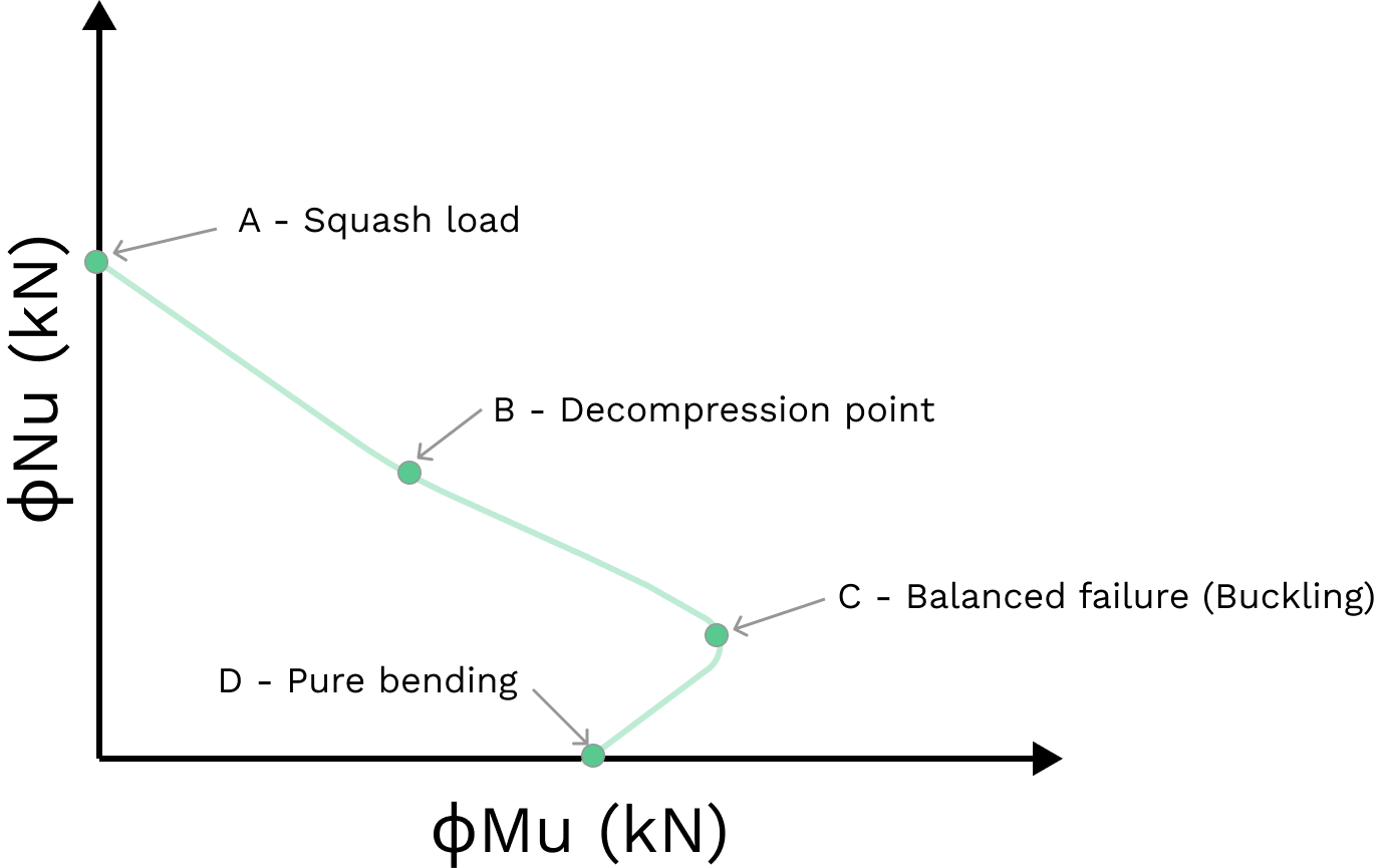
Columns are typically subject to combined compression and bending load and should be checked using an interaction curve, as per Cl 10.6.2 of AS3600:2018. An interaction curve is a graphical representation of the ultimate strength of a column's cross-section. It is defined by four key points (A, B, C and D on the below figure) which are design capacities that form the boundary of failure for a section subject to combined bending and axial load.
If the design forces \(N^*\) and \(M^*\) are within the region bound by the interaction curve, then the column is deemed to be safe.

Key Points on Interaction Curve
The four critical points on the interaction diagram describe a value for axial capacity, \(N_u \) and bending capacity, \(M_u \) for a given reinforcement arrangement based on a specific neutral axis depth. Note the design capacities are calculated using strain compatibility across the section. The maximum (ultimate) strain of concrete, \( ε_cu \) is 0.003 and the strain at yield for class 500N reinforcing bars is 0.0025.
A - Squash Load
The squash load, \(N_{uo}\) is the point where a column fails in pure compression. The concrete is at ultimate strain of 0.003 and, due to strain compatibility, the steel therefore has exceeded its yield strain and will be at yield strength.
.png)
\begin{aligned}
N_{uo} & = C_c + C_s \vphantom{\frac{0}{0}} \\
& \text{where} \vphantom{\frac{0}{0}} \\
C_c & = \alpha_1f'_c(A_g-A_{sc}) \vphantom{\frac{0}{0}} \\
C_s & = C_{s_{1}}+C_{s_{2}} \vphantom{\frac{0}{0}} \\
& = f_{sy}A_{sc} \vphantom{\frac{0}{0}} \\
k_u &= \infty \vphantom{\frac{0}{0}} \\
\end{aligned}
B - Decompression Point
The decompression point is where a column fails under combined bending and compression while providing no tensile capacity in the section. At this point, the strain in the tension reinforcement is zero and the extreme compressive fibre of the concrete is at ultimate strain of 0.003. The concrete section in tension is assumed to provide no resistance against tension.
.png)
$$ \begin{aligned}
N_u &= C_c + C_s \vphantom{\frac{0}{0}} \\
& \text{where} \vphantom{\frac{0}{0}} \\
C_c &= \alpha_2f'_c \times \gamma k_ud \times b \vphantom{\frac{0}{0}} \\
C_s &= \varepsilon_sE_sA_{sc} \vphantom{\frac{0}{0}} \\
k_u &= 1 \vphantom{\frac{0}{0}} \\
\end{aligned} $$
C - Balanced Failure
The balanced failure point is where a column fails under combined bending and compression by simultaneous crushing of the concrete and yielding of the reinforcement. At this point, the concrete is at ultimate strain, 0.003 and the outer steel strain reaches yield, 0.0025 and hence \(k_u\) is fixed at 0.545. The balanced failure point represents the maximum bending capacity of a column.
.png)
$$ \begin{aligned}
N_u &= C_c + C_s - T_s \vphantom{\frac{0}{0}} \\
& \text{where} \vphantom{\frac{0}{0}} \\
C_c &= \alpha_2f'_c \times \gamma k_ud \times b \vphantom{\frac{0}{0}} \\
C_s &= \varepsilon_{s1}E_sA_{sc} \vphantom{\frac{0}{0}} \\
T_s &= f_{sy}A_{st} \vphantom{\frac{0}{0}} \\
k_u &= 0.545 \vphantom{\frac{0}{0}} \\
\end{aligned} $$
D - Pure Bending
The pure bending point is where the column fails in bending without an external axial load. The column capacity is calculated in the same way as a doubly reinforced beam, taking moments about any point.
.png)
$$ \begin{aligned}
M_u &= C_c(\frac{\gamma k_ud}{2})+C_s(d_{sc})-T_s(d) \vphantom{\frac{0}{0}} \\
& \text{where} \vphantom{\frac{0}{0}} \\
C_c &= \alpha_2f'_c \times \gamma k_ud \times b \vphantom{\frac{0}{0}} \\
C_s &= \varepsilon_{s1}E_sA_{sc} \vphantom{\frac{0}{0}} \\
T_s &= f_{sy}A_{st} \vphantom{\frac{0}{0}} \\
\end{aligned} $$
