Learn how to design purlin and girts with a detailed step by step explanation.
Introduction
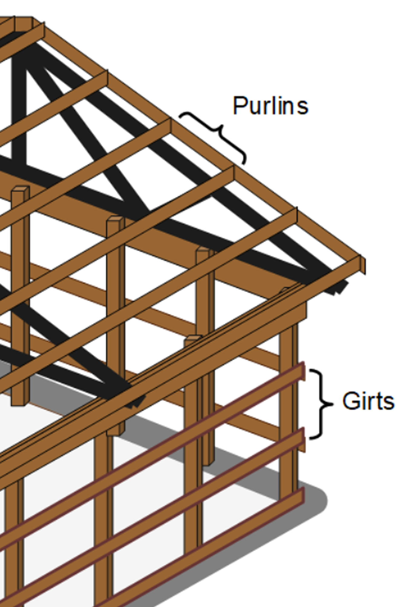
Purlins and girts are very common building elements, typically made from timber or steel. They are used to transfer roof or wall loads to the primary structural elements like roof rafters or vertical walls frames.
Timber purlins and girts are typically rectangular sections, while steel purlins and girts are typically cold-formed C- or Z- shaped sections.
- Purlins are structural members in roofs that support roof cladding and are themselves supported by roof rafters
- Girls are structural members in walls that support wall cladding and are themselves supported by wall frames
As a rule of thumb, purlins and girts are frequently proportioned for a depth-to-length ratio of 1/32.
Step by Step Design of Purlins and Girts
Step
The following factors should be considered when determining purlin and girt spacing:
- As a general rule of thumb, the maximum distance between purlins/girts should be about 1200 mm. In residential buildings, the typical distance is about 600 to 800 mm.
- Typically, the span direction of a purlin is against the slope of the roof and the span direction of a girt is horizontal.
- Openings for windows, doors, and skylights should be considered when establishing purlin/girt spacing. The primary purlin/girt members can also act as trimming members at openings.
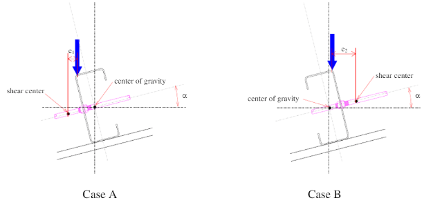
Here is a handy hint about how to orientate your Z-purlins on a sloped roof: When orientating purlins, remember “ducks always go uphill”

The orientation of purlins should provide a shorter distance from the shear center to the loading vector to minimize torsional impacts.
Step
For a steel purlin/girt, typically cold-formed C- or Z- sections are used and chosen from standard sections in manufacturing catalogues. For a timber purlin/girt, typically rectangular sections are used. The following should be considered:
- Use the rule of thumb to estimate the depth of the purlin/girt: depth = span/32
- Choose an available section size from the manufacturer's specifications with a suitable depth and design purpose.
- For steel purlins/girts, C- sections are used in simple and non-continuous spans, while Z- sections are used in continuous lines of purlins for lapping at internal supports.
- The manufacturer’s products should specify material properties and section properties used in design checks.
Step
Purlin and girts support cladding which is the first building element to have wind load imposed on it. Therefore, the main loads supported by purlins and girts are cladding (dead) loads and wind loads. Loads on structural members act over a tributary area/width. Figure below shows a typical roof arrangement in a building and the highlighted regions show the tributary area.
.png)
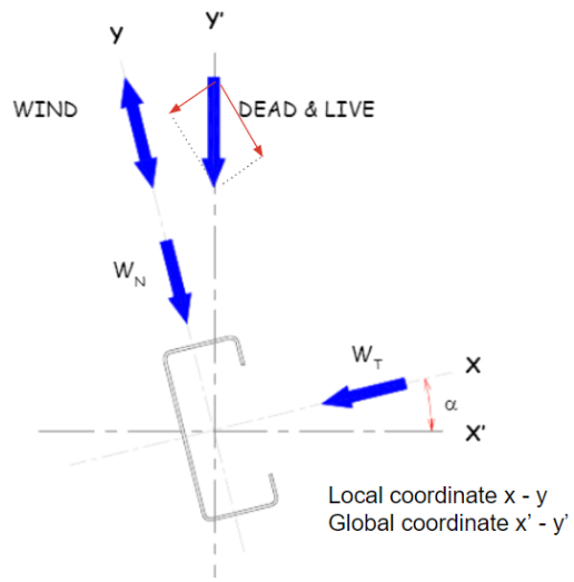
Purlins are typically inclined at an angle that follows the roof's slope. In the local axis system of a purlin, the x-axis is parallel to the purlin and the y-axis is perpendicular to the purlin.
.png)
Step
Dead loads include the self-weight of building elements (i.e. the purlins themselves) and superimposed dead loads (i.e. cladding, tanking, insulation, plaster, finishes, services, etc.). Live loads include human maintenance loads on a roof. Calculate the dead and live loads as line loads (kN/m) by multiplying their pressure (kPa) by the tributary width, which is the spacing of the purlins.
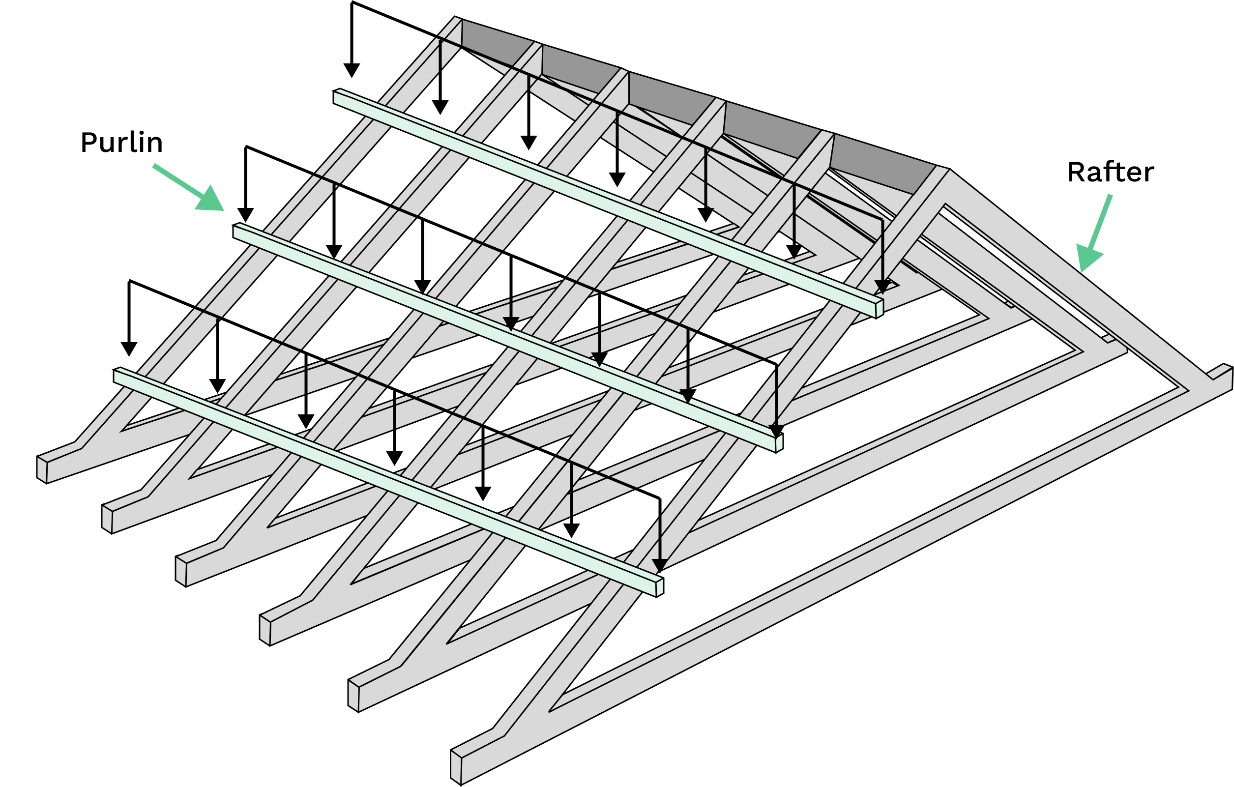
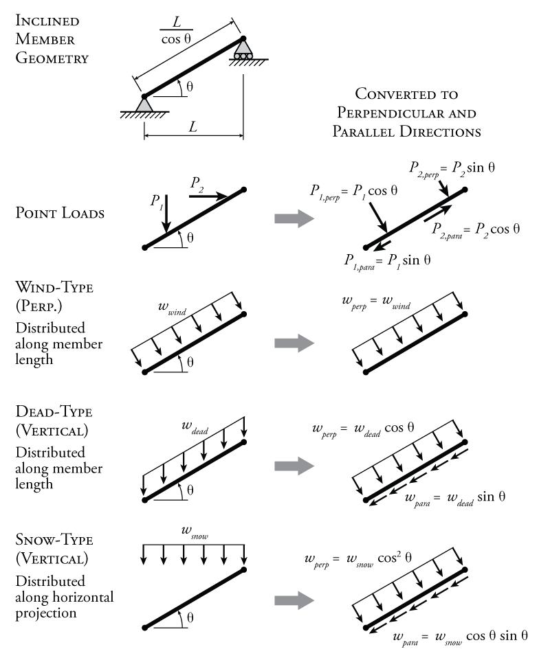
Dead and live loads act vertically (y-axis in the global axis) on a purlin or girt. For purlins on a sloped roof, there is therefore a tangential and normal component to the applied dead and live loads. These loads can be transformed to the local member axis using the roof slope.
Step
Wind load acts normal to a building surface. For roof purlins, this is on the y-axis of the local coordinate, so there is no need to convert it. Wind load depends heavily on the region the structure is located in, the type of structure, and topographic factors. Don't forget to check the suction wind load case.
The national design codes pertaining to the wind load calculation include:
- European Standard: Eurocode 1 Part 1 - 4
- Australian Standard: AS1170.2
- US Standard: ASCE 7 - 10
Calculate the uniformly distributed live load in kN/m along the purlin length by taking:
The same steps could be repeated if there are any other environmental loads.
Step
Each Design Code will propose a different methodology to calculate the load combinations with different design factors. Due to the design factor, more loads on the structure don’t mean it will be the critical condition, so all load combinations should be checked and the most critical condition chosen. Here are some common combinations:
- Dead Load only
- Dead Load + Live Load
- Dead Load + Wind Load
- Dead Load + Wind Load + Live Load
The national design codes pertaining to the calculation of load combinations:
- Australian Standard: AS1170.0
- European Standard: Eurocode 2
- US Code: ASCE 7 - 16
Choose the most critical scenario among those combinations to model and analyse the purlins. If the purlin system is simple enough, hand calculations can be performed.
Step
Usually, bending is the deciding design factor for purlins; that is why it is commonly checked first.
- For each loading combination chosen from Step 4, determine shear & bending forces along the x- and y- local axes. Don't forget, wind forces act normal to a roof surface so for forces in the the Y-axis, you don't need to transform the wind loads. You will need to transform the dead loads, like roof cladding to the local axis system since they act vertical due to gravity.
- Figure below illustrates some common beam configurations and the corresponding bending moment formula. Verify that bending moments are less than allowable or resistance stress limits.
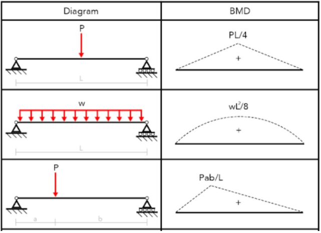
The national design codes pertaining to the bending strength design of steel and timber members are:
- Australian Standards: AS4100-Clause 5 (steel) & AS1720-Clause 2 (timber)
- US Standards: AISC360-10 (steel) & ASCE7-22 (timber)
- European Standards: EC3 (steel) & EC5 (timber)
❗If not verified, increase the width or height of the beam and recalculate.
Step
You can easily calculate the deflection of steel purlins and girts, by using standard beam deflection formulas.
.png)
The deflection of timber purlins and girts are a bit more complex. Timber experiences instantaneous deflection and long-term deflection caused my creep of the timber material. Final deflection is the sum of instantaneous deflection and the long-term (creep) deflection.
.png)
A secondary structural component like purlins will usually have the allowable deflection of L/180 (Eurocode). Different Design Codes might specify different allowable deflections
💡 Note: consider sag rods (or struts) for steel purlins and girts.
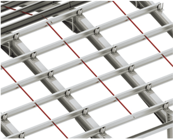
While cold-formed sections (particularly Z purlins or girts) can provide substantial material and cost savings due to their higher strength-to-weight ratios, it gives rise to conditions that may see these members deform under many loading conditions and fail by yielding or local buckling as a result of induced stresses. Sag rods (struts) may be added as lateral supports to provide alignment and reduce their tendency to twist and bend. Typical sag rods are 10-12mm in diameter. Generally, manufacturer’s tables will provide details on the application and installation of a bridging system such as sag rods.
After all the steps are verified, a safe and suitable beam dimensions can be achieved.
