Learn how to calculate the depth to the neutral axis of a reinforced concrete section under SLS in three different stages of concrete cracking.
Introduction
The neutral axis is an axis in the cross-section of a beam where there are no stresses or strain. When looking at reinforced concrete sections, the neutral axis shifts based on the extent of cracking assumed. The three common stages of cracking are:
- Uncracked, linear-elastic section
- Cracked, linear-elastic section
- Cracked, non-linear elastic section
This article will take you through how to calculate the three depths of the neutral axis according to AS3600:2018.
Why does the neutral axis exist?
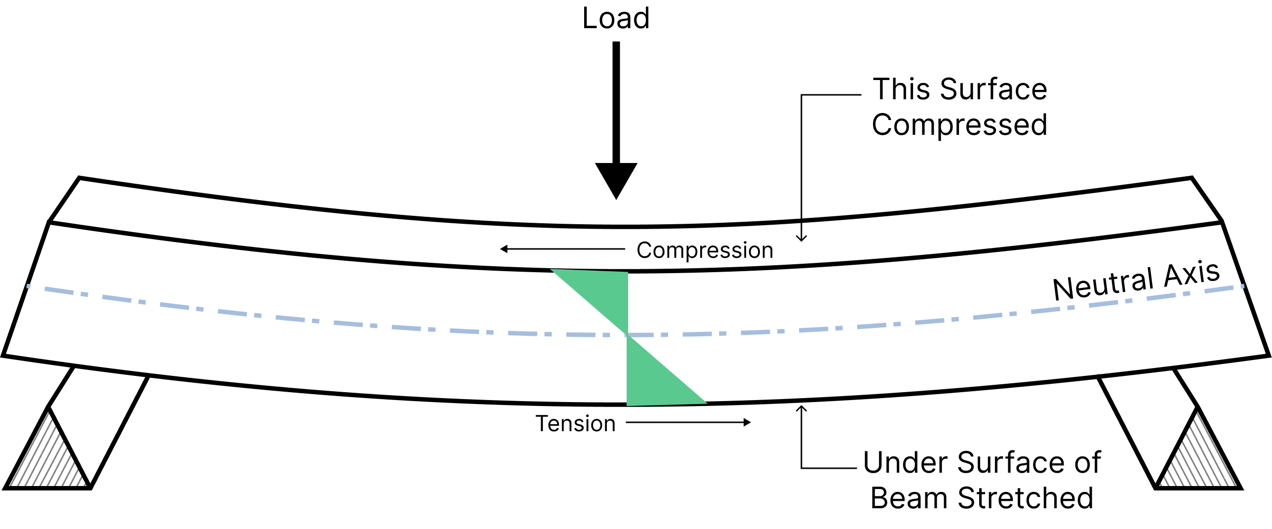
Picture a beam with an external load applied to it. When a beam is loaded, internal forces develop within it to maintain equilibrium. The internal forces in a beam have two components: shear forces in the vertical direction and normal force in the axis of the beam length. The resultant internal actions are a shear force and bending moment.

Centre: shear force in section
Right: resultant shear and bending moment
When a downwards force is applied to the top of a beam, the top surface is compressed while the bottom surface is in tension. Therefore there must be an axis in the beam’s cross-section that is neither stretched nor squashed i.e. where the internal stresses are zero. This axis is known as the neutral axis. The strain of the beam varies linearly from top of the section to the bottom and passes through zero at the neutral axis.

Why is it important to determine the neutral axis?
The concept of the neutral axis is fundamental when understanding and determining the flexural bending stresses and deflection of reinforced concrete beams. The neutral axis, \( d_n\) is an input parameter to the beam's ultimate flexural capacity, \( \phi M_u\) and an input parameter to the second moment of inertia equation, \( I\) for the beam's deflection.
The neutral axis indicates how much of the cross-section is in tension or compression. The further the neutral axis is from the extreme tensile fibre, the larger the area under tension and therefore the more tensile cracks there can be. Cracks begin propagating when the tensile stress reach the characteristic flexural tensile strength of the concrete. Concrete is inherently weaker in tension than compression, so steel reinforcements are used to increase the tensile strength of concrete.
Derivation
The location of the neutral axis depends on the geometry and cracking of the RC section. The neutral axis can be found using equilibrium of internal forces: \( \Sigma C-\Sigma T =0\) where \( \Sigma C\) and \( \Sigma T\) are the sums of compression and tension forces, respectively.
Three different stages can be defined for the determination of the neutral axis, as provided below.
To simplify the calculation, we "transform" our section into an equivalent homogeneous section, that is, a section with one material (concrete) rather then two materials (concrete and steel). The \( (n-1)A_{st}\) and \( (n-1)A_{sc}\) terms in the below equations, where \( n=\frac{E_s}{E_c}\) is the modular ratio, transforms the steel areas into equivalent concrete areas.
\( \textbf{1.} \) Uncracked and Linear Elastic
When the concrete is uncracked, the location of the neutral axis is the centre of the geometric centre of the transformed section. At this stage, the concrete section below the neutral axis demonstrates some tensile capacity.
This stage is commonly used under serviceability limit state for calculating deflections of uncracked concrete section.

$$\begin{aligned}
&\vphantom{\frac{0}{0}}\text{Compression in concrete, }C_c = \frac{1}{2} E_c \varepsilon_{comp} d_nb - E_c\varepsilon_{sc}A_{sc} \\
&\vphantom{\frac{0}{0}}\text{Compression in steel, } C_s = E_s\varepsilon_{sc}A_{sc} \\
&\vphantom{\frac{0}{0}}\text{Tension in concrete, }T_c = \frac{1}{2}E_c\varepsilon_{tens}(h-d_n)b - E_c\varepsilon_{st}A_{st} \\
&\vphantom{\frac{0}{0}}\text{Tension in steel, } T_s = E_s\varepsilon_{st}A_st \\
&\vphantom{\frac{0}{0}}\therefore C_c + C_s = T_c + T_s \\
\end{aligned}$$
Rearranging the above, the depth of the neutral axis, \( d_n\) is given by:
$$ d_n= \dfrac{\frac{h}{2}bh + d(n-1)A_{st}+d_{sc}(n-1)A_{sc}}{bh+(n-1)A_{st}+(n-1)A_{sc}} $$
\( \textbf{2.}\) Cracked and Linear Elastic
The section is cracked, but its behaviour is linear-elastic therefore the transformed area and force equilibrium method can be used.
This stage is commonly used under serviceability limit state for calculating deflections of cracked concrete section.

At this stage, the concrete section below the neutral axis does not contribute to tensile capacity. Hence:
$$\begin{aligned}
&\vphantom{\frac{0}{0}}\text{Compression in concrete, }C_c = \frac{1}{2} E_c\varepsilon_{comp}d_nb - E_c\varepsilon_{sc}A_{sc} \\
&\vphantom{\frac{0}{0}}\text{Compression in steel, } C_s = E_s\varepsilon_{sc}A_{sc}\\
&\vphantom{\frac{0}{0}}\text{Tension in concrete, }T_c =0 \\
&\vphantom{\frac{0}{0}}\text{Tension in steel, }T_s=E_s\varepsilon_{st}A_{st} \\
&\vphantom{\frac{0}{0}}\therefore C_c + C_s=T_s \\
\end{aligned}$$
The force equilibrium can be presented as a quadratic equation with respect to the depth of the neutral axis \( d_n\) and can be calculated as:
$$ \frac{1}{2}bd_n^2+[(n-1)A_{sc}+nA_{st}]d_n-[(n-1)A_{sc}d_{sc}+nA_{st}d_{st}]=0\ $$
\( \textbf{3.} \) Cracked and Inelastic
The section is cracked and has reached its ultimate strength capacity, therefore the stress distribution is non-linear. At this stage, rectangular stress block and force equilibrium method can be used.
This stage is commonly used under ultimate limit state for calculating the flexural capacity of a concrete section.

At this stage, the concrete section below the neutral axis also does not contribute to tensile capacity. Hence:
$$\begin{aligned}
&\vphantom{\frac{0}{0}}\text{Compression in concrete, } C_c = \alpha_2 f'_c \gamma \ b \ d_n \\
&\vphantom{\frac{0}{0}}\text{Compression in steel, }C_s = \varepsilon_{cu} E_s A_{sc} \frac{(d_n - d_{sc})}{d_n} \\
&\vphantom{\frac{0}{0}}\text{Tension in concrete, }T_c =0 \\
&\vphantom{\frac{0}{0}}\text{Tension in steel, } T_s = f_{sy}A_{st} \\
&\vphantom{\frac{0}{0}}\therefore C_c + C_s=T_s \\
\end{aligned}$$
The force equilibrium can be presented as a quadratic equation with respect to the depth of the neutral axis \( d_n\) and can be calculated as:
$$ \alpha_2 f'_c \gamma b {d_n}^2 + \varepsilon_{cu} E_s A_{sc} (d_n - d_{sc}) - f_{sy} A_{st} = 0 $$
.png)