.png)
Learn how to analyse and design different types of concrete slabs according to AS3600.
Introduction
Concrete slabs are one of the most essential structural components in modern construction, providing the foundation for floors, roofs and other horizontal surfaces. Among the various types of slabs, one-way slabs, two-way slabs and flat slabs are commonly used due to their versatility, strength and adaptability to different architectural and structural requirements.
Each slab type is designed to meet specific requirements based on factors such as span, load distribution, support configuration and construction requirements. In this article, each of the main slab types will be explained to understand the differences in structural behavior, design principles, and application.
One-way and two-way slabs are designed in the same way. The difference is how the design actions are determined. Although not specified in the standards, it is typical to define a two-way slab as:
Where:
: the length of the shorter slab span : the length of the longer slab span
Otherwise, the slab is considered a one-way slab.

For continuous slabs over two or more spans, design actions,
A summary of the simplified elastic analysis permitted by the code, is provided below for one-way slabs, two-way slabs and flat slabs.
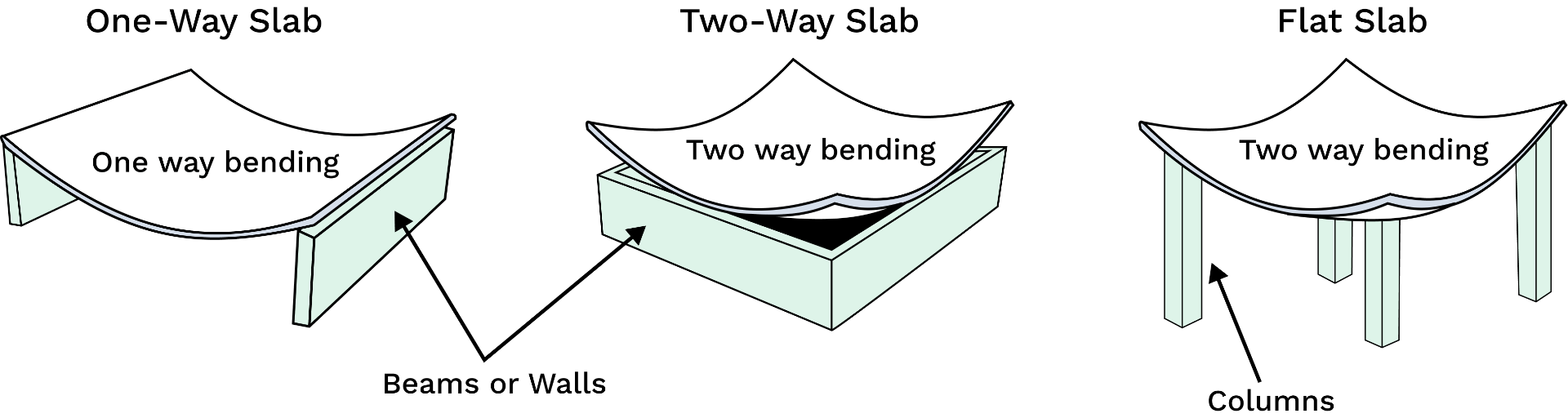
One way slabs are structural elements that primarily transfers loads in one direction. They're supported on two opposite sides and bending should occur along the longer span. The slab's behaviour can be thought of like a series of parallel beams spanning between the supports.
As per Clause 6.10.2 in AS3600, the design moments of a one-way slab using simplified elastic analysis is given by:
Where:
: depends on the location of the under consideration, see figures below : factored ULS design load per unit length : clear span length
.png)
As per the clause, the simplified method is valid provided:
- the ratio of the longer to the shorter length of any two adjacent spans does not exceed 1.2
- loads are uniformly distributed
- the slab has a constant cross-section
- reinforcement is arranged in accordance with Clause 9.1.3.2, which describes how much and the extent of top & bottom reinforcement with the slab span.
A two-way slab is a structural element supported on all four sides, distributing loads in two orthogonal directions. Bending occurs along both axes, making the slab more efficient in terms of strength and stiffness.
For two-way slab analysis, the code talks about edges of two-way slabs supported on four sides by beams or walls as either continuous or discontinuous:
- continuous edge means the slab is able to transfer load to the adjacent slab through that edge
- discontinuous edge means the slab is unable to transfer load to the adjacent slab through that edge, either because it is not detailed as continuous or it is the outside edge of a slab
.png)
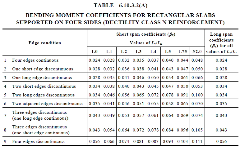
As per Clause 6.10.3, the positive design moments (i.e. sagging moments) at midspan of a two-way slab supported on four sides, using simplified elastic analysis is given by:
Where:
: moment coefficient : factored ULS design load per unit area : shorter span length
The table below provides bending moment coefficient for different type of edge conditions using AS3600.
👉 AS2600-2018 commentary provide equations for
As per Clause 6.10.3, the negative design moments (i.e. hogging moments) of a two-way slab using simplified elastic analysis is given by:
- at a continuous edge:
- at a discontinuous edge
The code says if the
For two-way slabs supported on all four sides by walls or beams, as per Clause 6.10.3, the simplified method is valid provided:
- loads are uniformly distributed
- reinforcement is arranged in accordance with Clause 9.1.3.3, which describes how much and the extent of top & bottom reinforcement with the slab span.
- openings in the slab are not big enough to adversely affect strength or stiffness
- if using reinforcement with ductility class L, slabs are supported by walls (not beams)
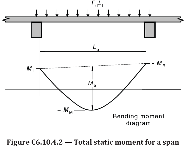
Flat slabs are defined as a two-way slab supported by columns. Clause 6.10.4 presents a simplified elastic method where the slab is analysed one panel (unit strip) at a time. A total static moment in each direction in each panel is calculated as:
Where:
: is the uniformly distributed design load per unit area (kPa) : is the width of the design strip, which for an interior design strip is taken as in the longer span and in the shorter span. For edge design strips, it is taken as in the longer span and in the shorter span. : is the effective span, which is taken as in the longer span and in the shorter span, for simplicity in our calculator
The total static moment is then shared between the supports (negative moments) and the mid-span (positive moments) as shown below.
At any critical section the design moment is determined by:
Where the factor is given in Tables 6.10.4.3(A) & (B).
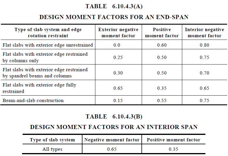
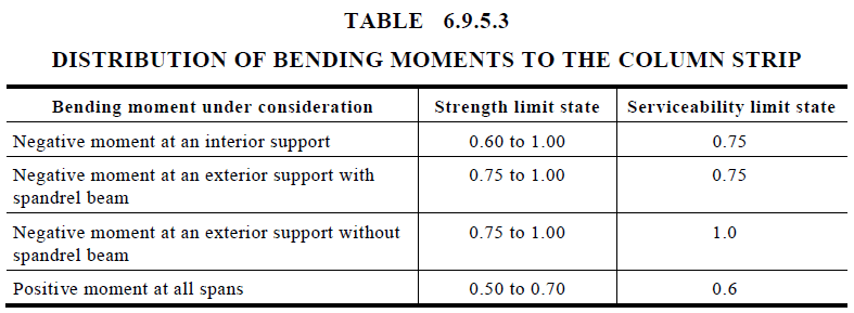
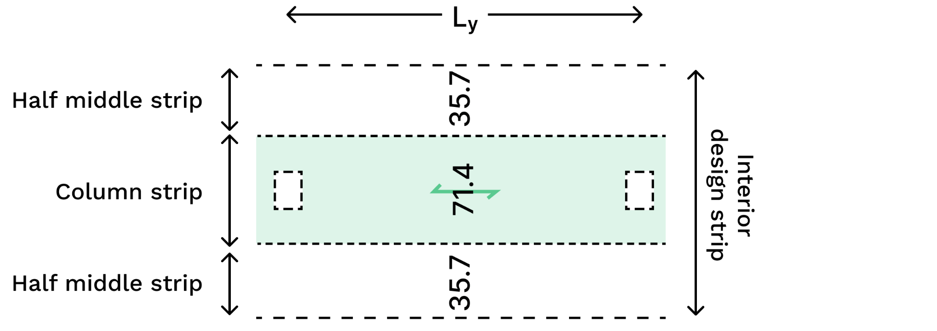
The positive and negative design moments are then distributed to the column and middle strips using the column strip moment factor in Table 6.9.5.3.
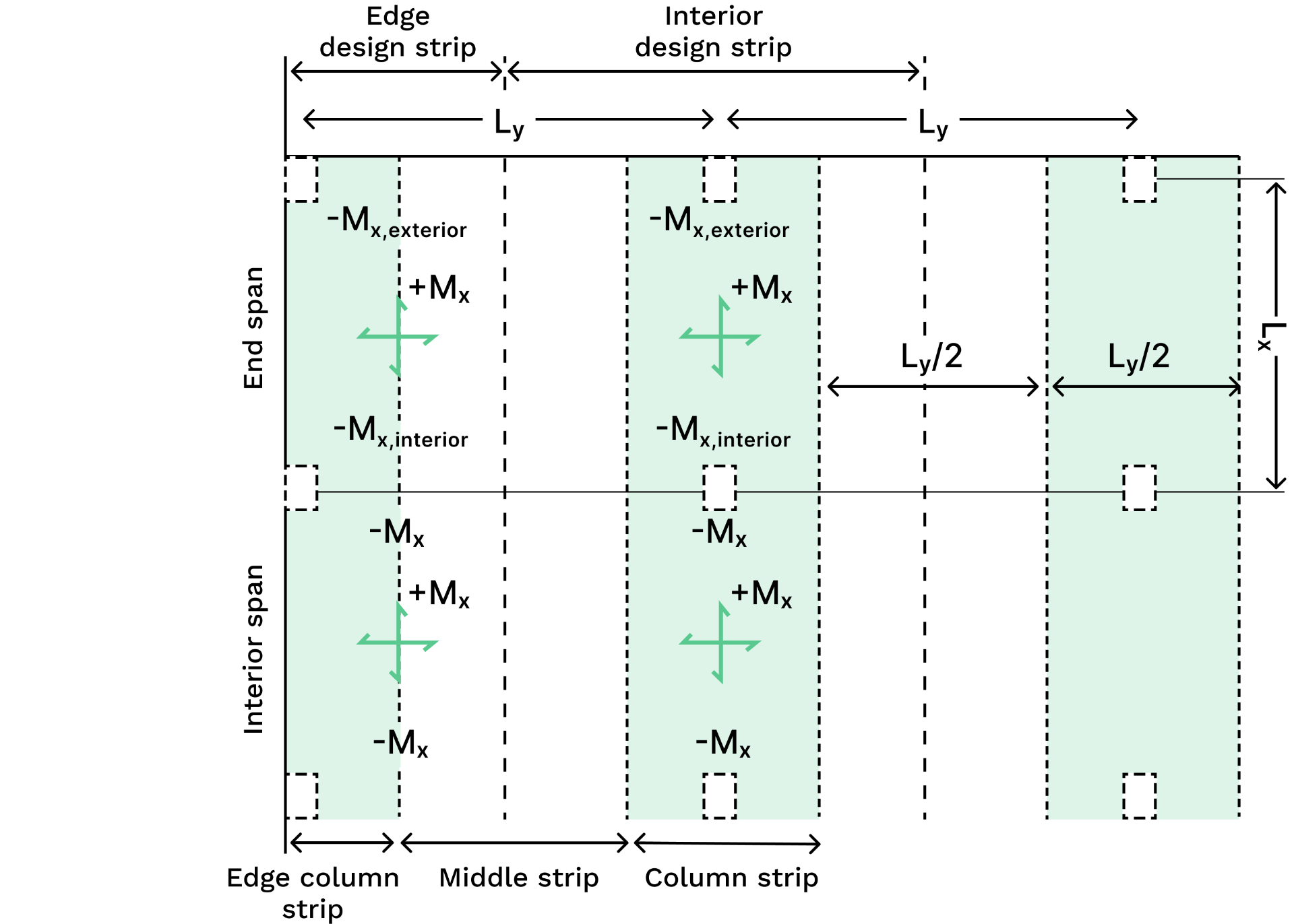
And so, all the unique design moments in the two directions, are illustrated in the below two figures.
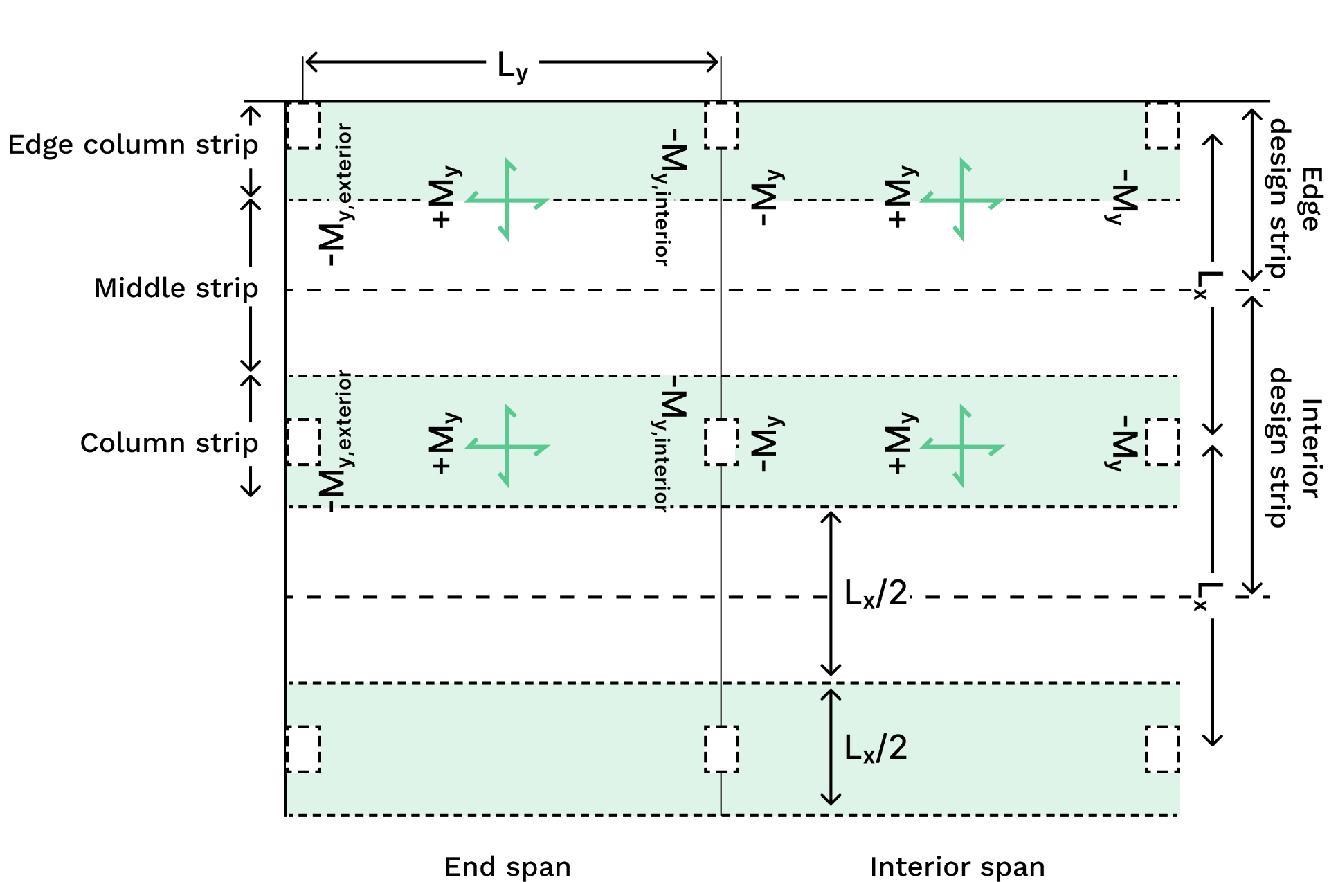
Let's break this down, for example: you could calculate an
So essentially, we end up the following unique design moments:
- 3x
- 2x
- 3x
- 2x
- 2x
That's 40 unique
The code says if the
For two-way slabs supported by columns (i.e. flat slabs), as per Clause 6.10.4, the simplified method is valid provided:
- loads are uniformly distributed
- at least two continuous spans in each direction
- support grid is roughly rectangular
- successive span lengths in each direction do not differ by more then 1/3 of the longer span, and the end span cannot be longer then the adjacent interior span
- lateral forces are resisted by shear walls or braced frames
- reinforcement with ductility class L is not used for flexural reinforcement
- reinforcement is arranged in accordance with Clause 9.1.3.4, which describes how much and the extent of top & bottom reinforcement with the slab span.
One-way, two-way and flat slabs are designed in the same way.
There are three main flexural checks that are required by Australian Standards:
- moment capacity checks
- ductility check
- minimum reinforcement check (i.e minimum strength check)
Slab moment capacity is calculated the same way as a beam.
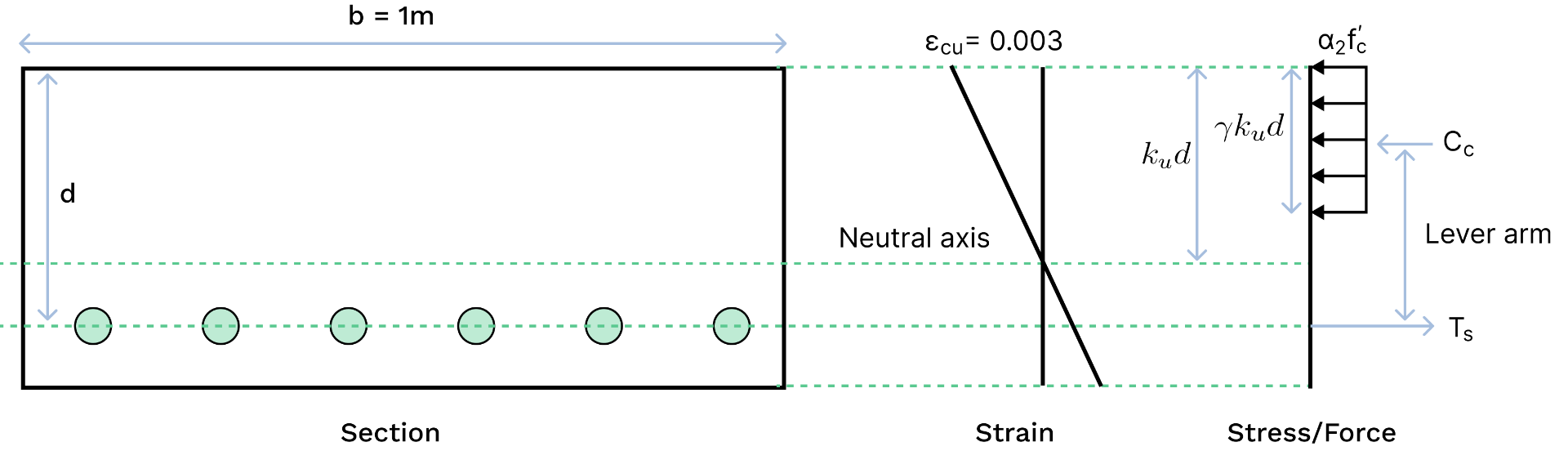
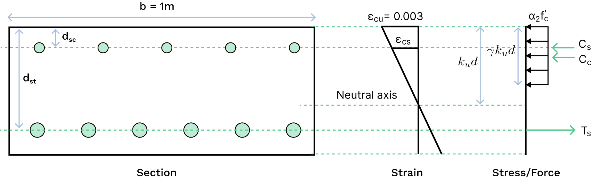
Let's use the example of a cross-section with top and bottom reinforcement. Using the Rectangular Stress Block as per Cl. 8.1.2, we can determine the moment capacity of a section by taking moments about the
Where:
: capacity reduction factor : depth ratio of neutral axis from the extreme compressive fibre to the bottom reinforcement, at ultimate strength : depth of Neutral Axis
Factor
Where :
is the stress in the reinforcement in the compressive zone is the strain in the reinforcement in the compressive zone, and is derived from similar triangles in the figure above is the maximum strain in the extreme compressive concrete fibre as per Clause 8.1.3
If
If
We then substitute
It is universal practice to ensure your concrete section is ductile. A ductile section means the reinforcement will yield before the concrete crushes, which is deemed a less dangerous failure mechanism since the failure occurs relatively slow compared to a sudden brittle failure. As per Cl 8.1.5, the code ensures ductile failure by checking:
where
Clause 8.1.6 specifies minimum strength requirements. Clause 9.1.1 specifies an adjustment to this for two-way slabs. Therefore, for reinforced concrete sections, the minimum strength requirement is deemed to be satisfied if
Where:
for one way slabs for two way slabs supported by columns at their corners for two way slabs supported by beams or walls on four sides
Since slab depths are typically small, shear is rarely a critical consideration. Except for flat slabs at column supports, punching shear must be checked. For punching shear calculation of a flat slab, check out our Concrete Punching Shear Calculator to AS3600.
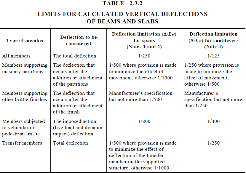
Clause 9.4 provides guidance for the deflection of slabs. A popular approach because of it's simplicity, is to follow Clause 9.4.4 which describes a deemed to conform span-to-depth ratio for deflections in RC slabs.
As per Clause 9.4.4, slab deflections are deemed to conform to code requirements if the following is satisfied:
Where :
: deflection limit, chosen by the user : the effective span, where in one-way slabs or two-way flat slabs , and in two way slabs supported on four side : effective depth of the slab : the effective design service load , given by:
where is from Table 4.1 in AS1170.0 and is taken at midspan for simply supported and continuous slabs for one way slabs nd two-way slabs supported on four sides, for multi-span two-way flat slab without drop panels, for multi-span two-way flat slab with drop panels for simply supported slabs, for an end span of continuous slab, for an interior span in a continuous slab
To use the above deflection check, Clause 9.4.4 states conditions that must be satisfied:
- uniform slab depth
- fully propped during construction
- loads are uniformly distributed and
- for two-way flat slabs with drop panels, drop panels must extend at least
- for continuous one-way slabs or two-way flat slabs, in adjoining spans, the ratio of the longer span to the shorter span does not exceed 1.2, and no end span is longer than an interior span