Determine the ultimate bearing capacity of different cases using Terzaghi and Meyerhof Methodology.
Introduction
The stability of a foundation depends on the soil's ability to support the loads transferred from the structure above. When the applied stress exceeds the soil's bearing capacity, failure occurs, compromising the foundation and potentially the structure itself. Understanding bearing failure modes is critical in geotechnical engineering to ensure safe and reliable foundation design.
The ultimate bearing capacity refers to the maximum pressure that the soil can sustain before failure, where the applied loads exceed the soil's supporting (bearing) capacity. The structure-soil interaction is affected by the soil's density and shear strength as well as the depth of the footing supporting the structure above.
In this design guide, we will explore bearing failure modes and their implications for determining bearing capacities. The information presented is based on Principles of Geotechnical Engineering 7th Edition by Braja M. Das.
\( \textbf{1}\) Modes of Bearing Failure
There are three primary modes of foundation bearing failure:
- General Shear Failure: A well-defined failure with distinct shear zones, typically occurring in dense soils.
- Local Shear Failure: Partial shear deformation observed in medium-dense or loose soils, where the failure is less pronounced.
- Punching Shear Failure: Occurs when the foundation "punches" through the soil, common in loose or soft soils with high compressibility.
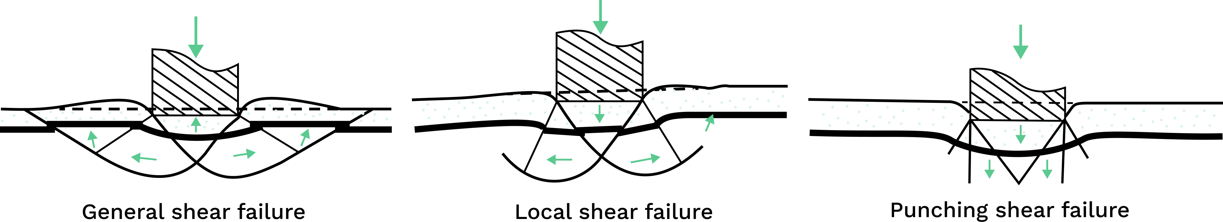
The three failure modes are characterised by their distinctive failure patterns and settlements.
\( \textbf{1.1}\) General Shear Failure
General shear failure manifests as an abrupt and devastating collapse marked by a distinct failure pattern. This involves the formation of a clearly defined failure surface extending from the edge of the footing to the ground surface. Notably, the failure is characterized by ground surface upheaval and footing tilting, unless there is an obstructing structure. Typically occurring when the foundation rests on compact sand and rigid clay, this failure scenario can have significant consequences.
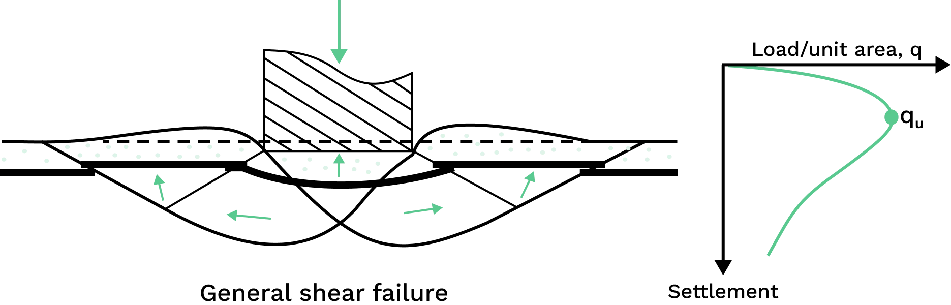
Settlement develops progressively with the incremental application of the load. Once the load per unit area attains the ultimate bearing capacity, a sudden failure occurs in the soil supporting the foundation. This failure is marked by the development of a failure surface within the soil extending to the ground surface, accompanied by noticeable bulging of adjacent soils on either side of the foundation.
\( \textbf{1.2}\) Localised Shear Failure
Localised shear failure occurs when the foundation is situated on soil with medium compaction, composed of sandy or clayey characteristics. The discernible failure pattern is only observable beneath the footing, resembling the general shear failure. This pattern entails visible wedge and slip surfaces at the footing's edges.
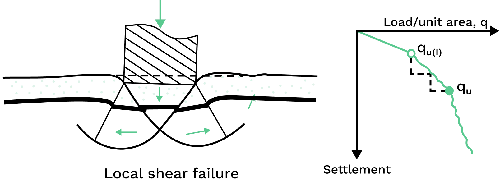
Upon reaching the ultimate bearing capacity, abrupt shifts occur in the foundation's movement, and subsequent incremental load increases lead to significant increases in foundation settlement. The failure surface subsequently extends outward from the foundation, and the load-settlement curve does not have a prominent peak.
\( \textbf{1.3}\) Punching Failure
Punching failure occurs when the foundation is significantly deep beneath the ground surface and is situated on loose soils with low compressibility. Unlike the above shear failures, there is no upheaval or tilting of adjacent soils, and the ground beneath essentially 'punches through' the soil when the capacity is exceeded.
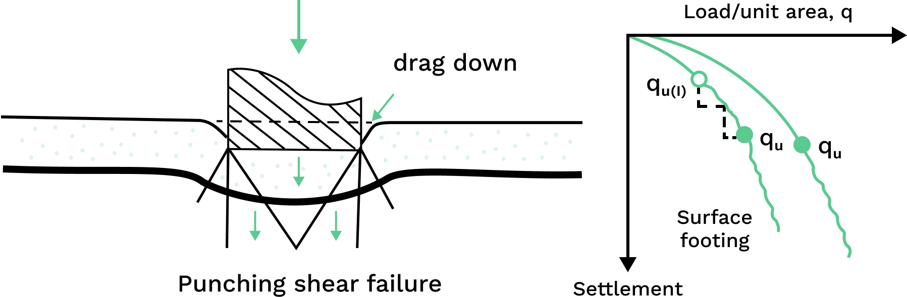
Unlike other failures, punching failure results in substantial settlement without a clearly defined ultimate bearing capacity. The compression of soil beneath the footing occurs suddenly with load increase and the failure surface does not extend above the ground surface. Hence, punching shear is difficult to observe and prevent.
\( \textbf{2}\) Calculating Soil Bearing Capacity
To accurately calculate the bearing capacity of a founding material, a thorough assessment of its properties and behavior is necessary. This involves conducting in-situ and lab tests, which propose challenges discussed in the next section.
Various empirical and theoretical methods have been proposed and refined to allow engineers to estimate (to a satisfactory standard) bearing capacities. In particular, Terzaghi and Meyerhof methods are widely used and a factor of safety (FoS) is incorporated into design, which reduces the ultimate bearing capacity. The FoS chosen generally varies anywhere from 1.5 ~ 3, and will depend on the uncertainty in soil properties. The allowable bearing capacity is calculated as follows:
$$ q_{\text{allowable}}\ =\dfrac{q_u}{\text{FoS}} $$
The Terzaghi method, developed before the Meyerhof method, assumes a relatively simple foundation shape and loading condition while accounting for multiple soil parameters. Terzaghi's ultimate bearing capacity is given by:
$$ q_u = K_c c N_c +K_q qN_q + K_\gamma \gamma_c B N_{\gamma} $$
In contrast, the Meyerhof method takes a more empirical approach and added factors to account for the footing shape, depth and load inclination. Meyerhof's ultimate bearing capacity is given by:
$$ {q_u=s_cN_c d_ci_cc'+s_qN_qd_qi_q\gamma D+\frac{1}{2}\gamma Bs_\gamma N_\gamma d_\gamma i_\gamma} $$
Let's look at both methods in more detail.
\( \textbf{2.1}\) Terzaghi Methodology
In 1943, Karl Terzaghi expanded on Prantl's 1921 study on the penetration of hard bodies on softer materials, the plastic failure theory. Terzaghi used this theory to determine the bearing capacity of soils for shallow foundations.
The Terzaghi method focuses on soil shear strength components, considering cohesion, effective stress and the angle of internal friction. Terzaghi's bearing capacity equations make the following assumptions:
- Width of the foundation is equal or greater than its depth (i.e. \(B>D\)), which means the foundation is considered a shallow foundation
- No sliding between foundation and soil
- Soil beneath the foundation is a homogenous, semi-infinite mass
- No applied moments, the applied load is compressive and is vertically applied to the foundation centroid
- A uniform surcharge, \( q = \gamma D_f\) can replace the weight of soil above the base of the footing
Terzaghi's ultimate bearing capacity is given by:
$$ q_u = K_ccN_c +K_qqN_q + {K_\gamma}{\gamma_c\ }BN_{\gamma} $$
Where:
\( \rlap{ c} \hspace{2.5em}\) : cohesion of the soil (kPa)
\( \rlap{ \gamma_c} \hspace{2.5em}\) : weight of the soil (kN/m^3) depending on case I , II or III, see below
\( \rlap{D} \hspace{2.5em}\) : depth of the footing below the ground level \( m\)
\( \rlap{B} \hspace{2.5em}\) : width of the footing (m)
\( \rlap{q} \hspace{2.5em}\) : overburden pressure which is the effective stress (kPa)
\( \rlap{N_c, \space N_q, \text{ and } N_\gamma} \hspace{7em}\) : bearing capacity factors, tabulated in Table 16.1 and 16.2 of Principles of Geotechnical Engineering 7th Edition by Braja M. Das
\( \rlap{K_c, \space K_q, \text{ and } K_\gamma} \hspace{7em}\) : constants and depend on the footing shape
\( \textbf{2.1.1}\) Adjustments to \( q_u\) based on failure mode
For general and local shear failure, the ultimate bearing capacity is dependent on the footing shape:
- Strip Footing : \( K_c=1\space,K_q=1\space, K_ \gamma=0.5\)
- Square footing: \( K_c=1.3\space,K_q=1\space, K_ \gamma=0.4\)
- Circular footing: \( K_c=1.3\space,K_q=1\space, K_ \gamma=0.3\)
Additionally, for local shear failure, it is assumed that the soil cohesion \(c\) is reduced to \(\bar{c}\) =\( \frac{2}{3}c\) and the soil friction is changed to \(tan{\bar{\phi}}=\frac{2}{3}\tan{\phi}\). The latter modification, results in modified bearing capacity factors \( N_c'\), \( N_q'\) and \( N_\gamma'\).
And so the ultimate bearing capacity for local shear failure is adjusted to:
$$ q_u = K_c\bar{c}N_c' +K_qqN_q' + {K_\gamma}{\gamma_c\ }BN_{\gamma}' $$
\( \textbf{2.1.2}\) Adjustments to \( q_u\) based on water table depth
The equations above assume the groundwater table depth, \( D\) is much greater than the footing width \( B\). However, in other cases wherein the water table is near or above the footing, the subsoil becomes saturated and the unit weight of the submerged soil is reduced, resulting in a decrease in the soil's ultimate bearing capacity.
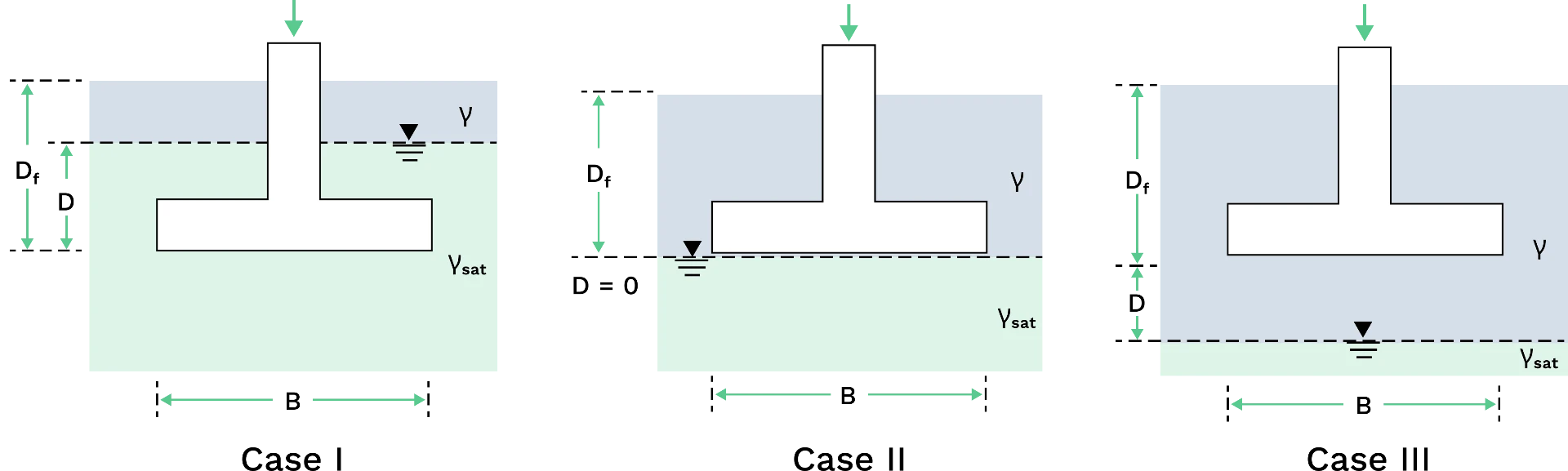
- Case I: water table above the footing base
$$ \begin{aligned}
q_u &= K_ccN_c +K_qqN_q + {K_\gamma}{\gamma'\ }BN_{\gamma} \vphantom{\frac{0}{0}} \\
\gamma'&=\gamma_{sat}-\gamma_w \vphantom{\frac{0}{0}} \\
q &=\gamma(D_f-D) + \gamma'D \vphantom{\frac{0}{0}}
\end{aligned}$$
- Case II: water table at the footing base
$$ \begin{aligned}
q_u &= K_ccN_c +K_qqN_q + {K_\gamma}{\gamma'\ }BN_{\gamma} \vphantom{\frac{0}{0}} \\
\gamma'&=\gamma_{sat}-\gamma_w \vphantom{\frac{0}{0}} \\
q &=\gamma(D_f) \vphantom{\frac{0}{0}}
\end{aligned}$$
- Case III: water table below the footing base
$$ \begin{aligned}
q_u &= K_ccN_c +K_qqN_q + {K_\gamma}{\gamma_{avg}\ }BN_{\gamma} \vphantom{\frac{0}{0}} \\
\text{For D}\leq\text{B: }\gamma_{avg}\ &=\dfrac{1}{B}[\gamma D+\gamma'(B-D)] \vphantom{\frac{0}{0}} \\
\text{For D > B: } \gamma_{avg}&=\gamma \vphantom{\frac{0}{0}} \\
q &=\gamma(D_f) \vphantom{\frac{0}{0}}
\end{aligned}$$
Where:
\(\rlap{ \gamma'} \hspace{2.5em}\) : effective unit weight of the soil
\(\rlap{ \gamma_{avg}} \hspace{2.5em}\) : average unit weight of soil
\(\rlap{ q } \hspace{2.5em}\) : overburden pressure
\( \textbf{2.2}\) Meyerhof Methodology
In 1963, Meyerhof introduced a solution for determining bearing capacity applicable to shallow foundations. The Meyerhof method takes a more empirical approach compared to Terzaghi, relying on field observations and simplified equations for estimating bearing capacity. Meyerhof added factors to the ultimate bearing capacity \(q_u\) to account for the footing shape, depth and load inclination:
- the shape factor determines the bearing capacity of circular or rectangular footing
- the depth factor accounts for the development of shearing resistance
- the inclination factor accounts for the inclination of the footing placement and the angle of load application
Meyerhof's ultimate bearing capacity is given by:
$$ {q_u=s_cN_c d_ci_cc'+s_qN_qd_qi_q\gamma D+\frac{1}{2}\gamma Bs_\gamma N_\gamma d_\gamma i_\gamma} $$
Where:
\( \rlap{ c'} \hspace{2.5em}\) : cohesion of the drained soil \(kP_a\)
\( \rlap{γ} \hspace{2.5em}\) : unit weight of the soil (kN/m^3)
\( \rlap{ D} \hspace{2.5em}\) : depth of the footing below the ground level (m)
\( \rlap{ B} \hspace{2.5em}\) : width of the footing (m)
\( \rlap{N_c, \space N_q, \text{ and } N_\gamma} \hspace{7em}\) : bearing capacity factors
\( \rlap{s_c, \space s_q, \text{ and } s_\gamma} \hspace{7em}\) : shape factors
\( \rlap{d_c, \space d_q, \text{ and } d_\gamma} \hspace{7em}\) : depth factors
\( \rlap{i_c, \space i_q, \text{ and } i_\gamma} \hspace{7em}\) : inclination factors
The bearing capacity factors (for soil cohesion, overburden pressure and unit weight of soil, respectively) are given by:
$$\begin{aligned}
N_c&=(N_q-1)\cot(\phi') \vphantom{\frac{0}{0}}\\
N_q&=\frac{1+\sin(\phi')}{1-\sin(\phi')}e^{\pi \tan(\phi')} \vphantom{\frac{0}{0}}\\
N_\gamma&=(N_q-1)\tan(1.4\phi') \vphantom{\frac{0}{0}}
\end{aligned}$$
The shape factors are given by:
$$ \begin{aligned}
s_c&=1+0.2\frac{1+\sin(\phi')}{1-\sin(\phi')}(\frac{B}{L}) \vphantom{\frac{0}{0}}\\
s_q=s_\gamma&=1+0.1\frac{1+\sin(\phi')}{1-\sin(\phi')}(\frac{B}{L}) \vphantom{\frac{0}{0}}
\end{aligned}$$
The depth factors are given by:
$$ \begin{aligned}
d_c&=1+0.2\sqrt{\frac{1+\sin(\phi')}{1-\sin(\phi')}}(\frac{D}{B}) \vphantom{\frac{0}{0}}\\
d_q = d_\gamma&=1+0.1\sqrt{\frac{1+\sin(\phi')}{1-\sin(\phi')}}(\frac{D}{B}) \vphantom{\frac{0}{0}}
\end{aligned}$$
The inclination factors are given by:
$$\begin{aligned}
i_c=i_q&=(1-\frac{\alpha}{90^o})^2 \vphantom{\frac{0}{0}}\\
i_\gamma&=(1-\frac{\alpha}{\phi'})^2 \vphantom{\frac{0}{0}}
\end{aligned} $$
\( \textbf{3}\) Soil testing
To accurately calculate the bearing capacity of a founding material, a thorough assessment of its properties and behavior is necessary. This includes conducting in-situ and lab tests, which propose the following challenges:
- Representativeness of samples - obtaining soil samples for testing involves extracting them from the ground, which may not accurately represent the in-situ conditions due to disturbance during sampling. Alterations in soil structure and water content during extraction can affect test results. Soil properties can vary widely within a site, and obtaining a limited number of samples may not capture this variability accurately. This variation can lead to uncertainties in design parameters.
- Time dependency - Some soil properties, such as consolidation and creep, are time-dependent. Laboratory tests conducted within short time frames might not capture long-term behavior accurately.
- Complexity of soil behaviour - soil behavior is complex and affected by numerous factors such as stress history, environmental conditions, and loading patterns. Simplified laboratory tests may not fully simulate these intricate conditions.
- Soil disturbance - the process of obtaining soil samples often disturbs the soil structure, altering its properties. Disturbance can affect the soil's natural state and consequently impact test results.